HP Omni Pro 110 Maintenance and Service Guide: HP Omni Pro 110 All-in-One PC - Page 51
WLAN Module
 |
View all HP Omni Pro 110 manuals
Add to My Manuals
Save this manual to your list of manuals |
Page 51 highlights
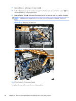
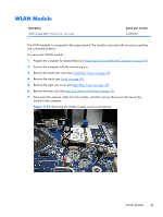
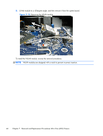
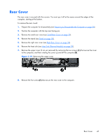
WLAN Module Description WLAN module (802.11b/g/n) (1x1 mini card) Spare part number 634906-001 The WLAN module is connected to the system board. The module is secured with two screws and has one connected antenna. To remove the WLAN module: 1. Prepare the computer for disassembly (see Preparing to Disassemble the Computer on page 28). 2. Position the computer with the rear facing you. 3. Remove the small rear cover (see Small Rear Cover on page 29). 4. Remove the stand (see Stand on page 30). 5. Remove the right rear cover (see Right Rear Cover on page 36). 6. Remove the heat sink (see Heat Sink (Thermal Module) on page 39). 7. Disconnect the antenna cable from the module, and then remove the screws that secure the module to the computer. Figure 7-14 Removing the WLAN module screws and antenna WLAN Module 43
-
 1
1 -
2
-
3
-
4
-
5
-
6
-
7
-
8
-
9
-
10
-
11
-
12
-
13
-
14
-
15
-
16
-
17
-
18
-
19
-
20
-
21
-
22
-
23
-
24
-
25
-
26
-
27
-
28
-
29
-
30
-
31
-
32
-
33
-
34
-
35
-
36
-
37
-
38
-
39
-
40
-
41
-
42
-
43
-
44
-
45
-
 46
46 -
 47
47 -
 48
48 -
 49
49 -
 50
50 -
 51
51 -
 52
52 -
 53
53 -
 54
54 -
 55
55 -
 56
56 -
57
-
58
-
59
-
60
-
61
-
62
-
63
-
64
-
65
-
66
-
67
-
68
-
69
-
70
-
71
-
72
-
73
-
74
-
75
-
76
-
77
-
78
-
79
-
80
-
81
-
82
-
83
-
84
-
85
-
86
-
87
-
88
-
89
-
90
-
91
-
92
-
93
-
94
-
95
 |
 |