HP Omni Pro 110 Maintenance and Service Guide: HP Omni Pro 110 All-in-One PC - Page 68
Drive Connectors, Preparing to Disassemble the Computer, on Small Rear Cover, Stand
 |
View all HP Omni Pro 110 manuals
Add to My Manuals
Save this manual to your list of manuals |
Page 68 highlights
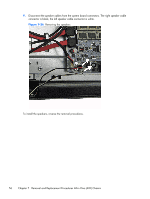
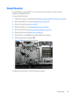
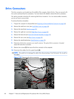
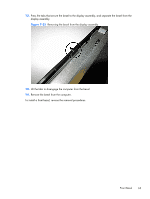
Drive Connectors The drive connectors are located near the middle of the computer, below the fan. They are secured with two screws and each has two connectors. You must remove the shield to remove the drive connectors. This section provides instructions for removing both drive connectors. You can remove either connector; you do not have to remove both. To remove the drive connectors: 1. Prepare the computer for disassembly (see Preparing to Disassemble the Computer on page 28). 2. Remove the small rear cover (see Small Rear Cover on page 29). 3. Remove the stand (see Stand on page 30). 4. Remove the right rear cover (see Right Rear Cover on page 36). 5. Remove the heat sink (see Heat Sink (Thermal Module) on page 39). 6. Remove the rear cover (see Rear Cover on page 47). 7. Remove the stand bracket (see Stand Bracket on page 59). 8. Determine which drive connector you need to remove. The optical drive connector is located above the hard drive connector. 9. Remove two screws (1) that secure the drive connector to the computer. 10. Disconnect the cables from the system board (2). NOTE: Be careful not to damage the cable when disconnecting it from the board. Do not pull on the cables. Figure 7-29 Removing the drive connectors 60 Chapter 7 Removal and Replacement Procedures All-in One (AIO) Chassis
-
 1
1 -
2
-
3
-
4
-
5
-
6
-
7
-
8
-
9
-
10
-
11
-
12
-
13
-
14
-
15
-
16
-
17
-
18
-
19
-
20
-
21
-
22
-
23
-
24
-
25
-
26
-
27
-
28
-
29
-
30
-
31
-
32
-
33
-
34
-
35
-
36
-
37
-
38
-
39
-
40
-
41
-
42
-
43
-
44
-
45
-
46
-
47
-
48
-
49
-
50
-
51
-
52
-
53
-
54
-
55
-
56
-
57
-
58
-
59
-
60
-
61
-
62
-
 63
63 -
 64
64 -
 65
65 -
 66
66 -
 67
67 -
 68
68 -
 69
69 -
 70
70 -
 71
71 -
 72
72 -
 73
73 -
74
-
75
-
76
-
77
-
78
-
79
-
80
-
81
-
82
-
83
-
84
-
85
-
86
-
87
-
88
-
89
-
90
-
91
-
92
-
93
-
94
-
95
 |
 |