HP Omni Pro 110 Maintenance and Service Guide: HP Omni Pro 110 All-in-One PC - Page 94
Torx T15 screwdriver - parts and supplies
 |
View all HP Omni Pro 110 manuals
Add to My Manuals
Save this manual to your list of manuals |
Page 94 highlights
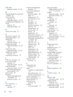
LVDS cable spare part number 24, 26 M mass storage devices, spare part numbers 25 memory module removing 37 spare part numbers 24, 27 microphone pin assignments 80 mouse cleaning 20 spare part numbers 25 N numeric error codes 67 O opening the computer 28 operating guidelines 18 optical drive removing 32 spare part numbers 25 optical drive bracket spare part numbers 25, 27, 32 optical drive cable spare part number 24, 26 optical drive connector removing 60 overheating, prevention 18 P POST error messages 66 power button board removing 51 spare part number 24, 26 power button/LED spare part number 24, 27 power cord set requirements country specific 83 power supply 84 processor removal and replacement procedures 41 spare part numbers 24 R rear components 4 rear cover removing 47 removal and replacement processor 41 removal and replacement procedures All-in One chassis 28 bezel 61 display panel 64 drive connectors 60 fan 53 front bezel 61 hard drive 34 hard drive connector 60 heat sink 39 inverter board 49 left rear cover 31 memory 37 optical drive 32 optical drive connector 60 power button board 51 preparing to disassemble the computer 28 rear cover 47 right rear cover 36 small rear cover 29 speakers 55 stand 30 stand bracket 59 system board 57 system board shield 52 thermal module 39 webcam module 45 WLAN module 43 right rear cover removing 36 S safety precautions cleaning 19 SATA connectors on system board 13 data cable pinouts 13 hard drive characteristics 13 screws, correct size 21 service considerations 21 side components 4 small rear cover removing 29 software servicing computer 21 spare part number tamper-resistent wrench 21 Torx T-15 screwdriver 21 speaker spare part number 27, 55 spare part numbers 24 speakers removing 55 specifications computer 84 stand removing 30 stand bracket removing 59 static electricity 16 system board removing 57 SATA connectors 13 spare part numbers 24, 26 system board shield removing 52 T tamper-proof screws tool 21 temperature control 18 thermal module removing 39 thermal module, spare part number 24, 26, 27 thermal pad, DIMM spare part number 27 thermal pad, VRM spare part number 27 tools, servicing 21 Torx T15 screwdriver 21 U USB pin assignments 80 V ventilation, proper 18 W webcam cable spare part number webcam module removing 45 spare part number WLAN antenna cable spare part number 24, 26 24, 26 24, 27 86 Index
-
 1
1 -
2
-
3
-
4
-
5
-
6
-
7
-
8
-
9
-
10
-
11
-
12
-
13
-
14
-
15
-
16
-
17
-
18
-
19
-
20
-
21
-
22
-
23
-
24
-
25
-
26
-
27
-
28
-
29
-
30
-
31
-
32
-
33
-
34
-
35
-
36
-
37
-
38
-
39
-
40
-
41
-
42
-
43
-
44
-
45
-
46
-
47
-
48
-
49
-
50
-
51
-
52
-
53
-
54
-
55
-
56
-
57
-
58
-
59
-
60
-
61
-
62
-
63
-
64
-
65
-
66
-
67
-
68
-
69
-
70
-
71
-
72
-
73
-
74
-
75
-
76
-
77
-
78
-
79
-
80
-
81
-
82
-
83
-
84
-
85
-
86
-
87
-
88
-
 89
89 -
 90
90 -
 91
91 -
 92
92 -
 93
93 -
 94
94 -
 95
95
 |
 |
