HP Omni Pro 110 Maintenance and Service Guide: HP Omni Pro 110 All-in-One PC - Page 59
Power Button Board
 |
View all HP Omni Pro 110 manuals
Add to My Manuals
Save this manual to your list of manuals |
Page 59 highlights
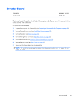
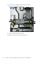
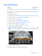
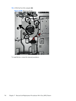
Power Button Board Description Power button board Spare part number 651585-001 The power button board is mounted on the left side of the computer. It is secured with two screws and has one connector. To remove the power button board: 1. Prepare the computer for disassembly (see Preparing to Disassemble the Computer on page 28). 2. Remove the small rear cover (see Small Rear Cover on page 29). 3. Remove the stand (see Stand on page 30). 4. Remove the right rear cover (see Right Rear Cover on page 36). 5. Remove the heat sink (see Heat Sink (Thermal Module) on page 39). 6. Remove the rear cover (see Rear Cover on page 47). 7. Remove the two screws (1) that secure the board to the computer. 8. Disconnect the cables from the board (2). NOTE: Be careful not to damage the cable when disconnecting it from the board. Do not pull on the wires. Figure 7-22 Removing the power button board 9. Remove the board from the computer. To install the power button board, reverse the removal procedures. Power Button Board 51
-
 1
1 -
2
-
3
-
4
-
5
-
6
-
7
-
8
-
9
-
10
-
11
-
12
-
13
-
14
-
15
-
16
-
17
-
18
-
19
-
20
-
21
-
22
-
23
-
24
-
25
-
26
-
27
-
28
-
29
-
30
-
31
-
32
-
33
-
34
-
35
-
36
-
37
-
38
-
39
-
40
-
41
-
42
-
43
-
44
-
45
-
46
-
47
-
48
-
49
-
50
-
51
-
52
-
53
-
 54
54 -
 55
55 -
 56
56 -
 57
57 -
 58
58 -
 59
59 -
 60
60 -
 61
61 -
 62
62 -
 63
63 -
 64
64 -
65
-
66
-
67
-
68
-
69
-
70
-
71
-
72
-
73
-
74
-
75
-
76
-
77
-
78
-
79
-
80
-
81
-
82
-
83
-
84
-
85
-
86
-
87
-
88
-
89
-
90
-
91
-
92
-
93
-
94
-
95
 |
 |