HP Omni Pro 110 Maintenance and Service Guide: HP Omni Pro 110 All-in-One PC - Page 72
Display Panel
 |
View all HP Omni Pro 110 manuals
Add to My Manuals
Save this manual to your list of manuals |
Page 72 highlights
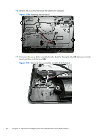
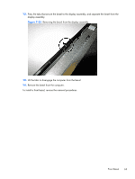
Display Panel Description Display, 20-inch, non-glare Spare part number 646794-001 The display panel is secured with 4 screws. To remove the display panel: 1. Prepare the computer for disassembly (see Preparing to Disassemble the Computer on page 28). 2. Remove the small rear cover (see Small Rear Cover on page 29). 3. Remove the stand (see Stand on page 30). 4. Remove the right rear cover (see Right Rear Cover on page 36). 5. Remove the heat sink (see Heat Sink (Thermal Module) on page 39). 6. Remove the rear cover (see Rear Cover on page 47). 7. Remove the system board shield (see System Board Shield on page 52). 8. Remove the system board (see System Board on page 57). 9. Remove the stand bracket (see Stand Bracket on page 59). 10. Remove the drive connectors (see Drive Connectors on page 60). 11. Remove the front bezel (see Front Bezel on page 61). 64 Chapter 7 Removal and Replacement Procedures All-in One (AIO) Chassis
-
 1
1 -
2
-
3
-
4
-
5
-
6
-
7
-
8
-
9
-
10
-
11
-
12
-
13
-
14
-
15
-
16
-
17
-
18
-
19
-
20
-
21
-
22
-
23
-
24
-
25
-
26
-
27
-
28
-
29
-
30
-
31
-
32
-
33
-
34
-
35
-
36
-
37
-
38
-
39
-
40
-
41
-
42
-
43
-
44
-
45
-
46
-
47
-
48
-
49
-
50
-
51
-
52
-
53
-
54
-
55
-
56
-
57
-
58
-
59
-
60
-
61
-
62
-
63
-
64
-
65
-
66
-
 67
67 -
 68
68 -
 69
69 -
 70
70 -
 71
71 -
 72
72 -
 73
73 -
 74
74 -
 75
75 -
 76
76 -
 77
77 -
78
-
79
-
80
-
81
-
82
-
83
-
84
-
85
-
86
-
87
-
88
-
89
-
90
-
91
-
92
-
93
-
94
-
95
 |
 |