HP Pavilion a400 HP Pavilion Desktop PC - (English) Users Guide PAV SEA/ANZ/IN - Page 133
add-in cards
 |
View all HP Pavilion a400 manuals
Add to My Manuals
Save this manual to your list of manuals |
Page 133 highlights
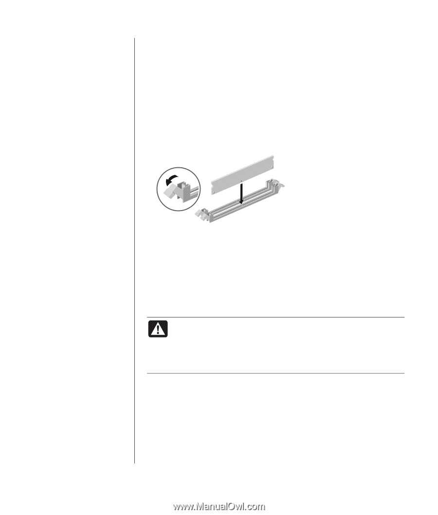
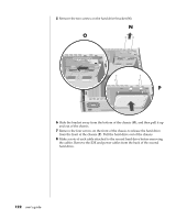
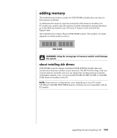
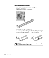
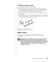
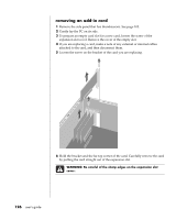
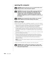
installing a memory module 1 See "removing a memory module" on page 124. 2 Holding the new memory module by its edges only, remove it from the antistatic packaging. (Avoid touching the memory chips or the gold contacts on the module.) The memory module has one or two small notches on the lower edge, which fit into raised bumps in the memory socket. 3 Hold the memory module in alignment with the socket, aligning the notches with the bumps. 4 Push straight down on top of the memory module until it is fully seated in the socket. The retaining clips on the ends of the socket automatically lock it into position when the memory module is fully seated. 5 Replace any cabling that was removed. 6 Replace the side panel. See page 106. add-in cards At some point, you may want to add a PCI or an AGP card to the PC to accommodate a new component, such as a scanner, or to upgrade an existing card. WARNING: Do not overload the system by installing add-in cards that draw excessive current. The system is designed to provide 2 amps (average) of +5 V power for each board/card in the PC. The total +5 V current draw in a fully loaded system (one with all addin card slots filled) must not exceed the total number of slots multiplied by 2 amps. upgrading and servicing the pc (1) 125
-
 1
1 -
2
-
3
-
4
-
5
-
6
-
7
-
8
-
9
-
10
-
11
-
12
-
13
-
14
-
15
-
16
-
17
-
18
-
19
-
20
-
21
-
22
-
23
-
24
-
25
-
26
-
27
-
28
-
29
-
30
-
31
-
32
-
33
-
34
-
35
-
36
-
37
-
38
-
39
-
40
-
41
-
42
-
43
-
44
-
45
-
46
-
47
-
48
-
49
-
50
-
51
-
52
-
53
-
54
-
55
-
56
-
57
-
58
-
59
-
60
-
61
-
62
-
63
-
64
-
65
-
66
-
67
-
68
-
69
-
70
-
71
-
72
-
73
-
74
-
75
-
76
-
77
-
78
-
79
-
80
-
81
-
82
-
83
-
84
-
85
-
86
-
87
-
88
-
89
-
90
-
91
-
92
-
93
-
94
-
95
-
96
-
97
-
98
-
99
-
100
-
101
-
102
-
103
-
104
-
105
-
106
-
107
-
108
-
109
-
110
-
111
-
112
-
113
-
114
-
115
-
116
-
117
-
118
-
119
-
120
-
121
-
122
-
123
-
124
-
125
-
126
-
127
-
 128
128 -
 129
129 -
 130
130 -
 131
131 -
 132
132 -
 133
133 -
 134
134 -
 135
135 -
 136
136 -
 137
137 -
 138
138 -
139
-
140
-
141
-
142
-
143
-
144
-
145
-
146
-
147
-
148
-
149
-
150
-
151
-
152
-
153
-
154
-
155
-
156
-
157
-
158
-
159
-
160
-
161
-
162
-
163
-
164
-
165
-
166
-
167
-
168
 |
 |