HP Surestore Tape Library Model 20/700 HP Surestore Bridge FC 2/1 LV and FC 4/ - Page 15
Back Panel of the HP Surestore Bridge FC 2/1 LV,
 |
View all HP Surestore Tape Library Model 20/700 manuals
Add to My Manuals
Save this manual to your list of manuals |
Page 15 highlights
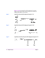
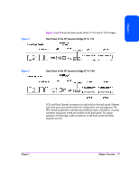
Chapter 1 Figure 4 Figures 4 and 5 show the back panels of the 2/1 LV and 4/1 HV bridges. Back Panel of the HP Surestore Bridge FC 2/1 LV Figure 5 Back Panel of the HP Surestore Bridge FC 4/1 HV SCSI and Fibre Channel connectors can be found on the back panel. Ethernet and serial ports provide the means for configuration and management. The LED indicators (operation indicators) provide basic status information. A power connector and power switch are located on the back panel. For proper operation of the bridge, cable connections on the back panel should be properly secured. Chapter 1 Chapter Overview 17
-
 1
1 -
2
-
3
-
4
-
5
-
6
-
7
-
8
-
9
-
 10
10 -
 11
11 -
 12
12 -
 13
13 -
 14
14 -
 15
15 -
 16
16 -
 17
17 -
 18
18 -
 19
19 -
 20
20 -
21
-
22
-
23
-
24
-
25
-
26
-
27
-
28
-
29
-
30
-
31
-
32
-
33
-
34
-
35
-
36
-
37
-
38
-
39
-
40
-
41
-
42
-
43
-
44
-
45
-
46
-
47
-
48
-
49
-
50
-
51
-
52
-
53
-
54
-
55
-
56
-
57
-
58
-
59
-
60
-
61
-
62
-
63
-
64
-
65
-
66
-
67
-
68
-
69
-
70
-
71
-
72
-
73
-
74
-
75
-
76
-
77
-
78
-
79
-
80
-
81
-
82
-
83
-
84
-
85
-
86
-
87
-
88
-
89
-
90
-
91
-
92
-
93
-
94
-
95
-
96
-
97
-
98
-
99
-
100
-
101
-
102
-
103
-
104
-
105
-
106
-
107
-
108
-
109
-
110
-
111
-
112
-
113
-
114
-
115
-
116
-
117
-
118
-
119
-
120
-
121
-
122
-
123
-
124
-
125
-
126
-
127
-
128
-
129
-
130
-
131
-
132
-
133
-
134
-
135
-
136
-
137
-
138
-
139
-
140
-
141
-
142
-
143
-
144
-
145
-
146
-
147
-
148
-
149
-
150
-
151
-
152
-
153
-
154
-
155
-
156
-
157
-
158
-
159
-
160
-
161
-
162
-
163
-
164
-
165
-
166
-
167
-
168
-
169
-
170
-
171
-
172
-
173
-
174
-
175
-
176
-
177
-
178
-
179
-
180
-
181
-
182
-
183
-
184
-
185
-
186
-
187
-
188
-
189
-
190
-
191
-
192
-
193
-
194
-
195
-
196
-
197
-
198
-
199
-
200
-
201
-
202
-
203
-
204
-
205
-
206
-
207
-
208
-
209
-
210
-
211
-
212
-
213
-
214
-
215
-
216
-
217
-
218
-
219
-
220
-
221
-
222
-
223
-
224
-
225
-
226
-
227
-
228
-
229
-
230
-
231
-
232
-
233
-
234
-
235
-
236
-
237
-
238
-
239
-
240
-
241
-
242
-
243
-
244
-
245
-
246
-
247
-
248
-
249
-
250
-
251
-
252
-
253
-
254
-
255
-
256
-
257
-
258
-
259
-
260
 |
 |

Chapter 1
Chapter Overview
17
Chapter 1
Figures 4
and
5
show the back panels of the 2/1 LV and 4/1 HV bridges.
Figure 4
Back Panel of the HP Surestore Bridge FC 2/1 LV
Figure 5
Back Panel of the HP Surestore Bridge FC 4/1 HV
SCSI and Fibre Channel connectors can be found on the back panel. Ethernet
and serial ports provide the means for configuration and management. The
LED indicators (operation indicators) provide basic status information. A power
connector and power switch are located on the back panel. For proper
operation of the bridge, cable connections on the back panel should be
properly secured.