IBM 88614RX Maintenance Manual - Page 14
Server controls, LEDs, and power, Front view, USB port, Operator information panel
 |
UPC - 000435172662
View all IBM 88614RX manuals
Add to My Manuals
Save this manual to your list of manuals |
Page 14 highlights
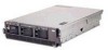
Server controls, LEDs, and power This section describes the controls and light-emitting diodes (LEDs) and how to turn the server on and off. Front view The following illustration shows the controls, LEDs, and connectors on the front of the server. USB port Operator information panel CD-ROM activity LED Hard disk drive filler panel Hard disk drive activity LED Hard disk drive status LED Diskette drive activity LED USB port: You can connect a USB device to this connector. Operator information panel: This panel contains controls, indicators, and a USB port. Swing it open to see the light path diagnostics LEDs on the side surface. Details about the operator information panel are listed below. Power-on LED System-error LED Power-control button Reset button USB connector SCSI activity LED Information LED Locator LED Release latch Operator information panel Power-control button: Press this button to turn the server on and off manually. A power-control-button shield comes with your server. You can install this disk-shaped shield to prevent the server from being turned off accidentally. Power-on LED: When this LED is lit and not flashing, it indicates that the server is turned on. When this LED is flashing, it indicates that the server is turned off and still connected to an ac power source. When this LED is off, it indicates that ac power is not present, or the power supply or the LED itself has failed. A power LED is also on the rear of the server. Note: If this LED is off, it does not mean that there is no electrical power in the server. The LED might be burned out. To remove all electrical power from the server, you must disconnect the power cord from the electrical outlet. 4 IBM xSeries 365 Types 8861, 8862: Hardware Maintenance Manual and Troubleshooting Guide
-
 1
1 -
2
-
3
-
4
-
5
-
6
-
7
-
8
-
 9
9 -
 10
10 -
 11
11 -
 12
12 -
 13
13 -
 14
14 -
 15
15 -
 16
16 -
 17
17 -
 18
18 -
 19
19 -
20
-
21
-
22
-
23
-
24
-
25
-
26
-
27
-
28
-
29
-
30
-
31
-
32
-
33
-
34
-
35
-
36
-
37
-
38
-
39
-
40
-
41
-
42
-
43
-
44
-
45
-
46
-
47
-
48
-
49
-
50
-
51
-
52
-
53
-
54
-
55
-
56
-
57
-
58
-
59
-
60
-
61
-
62
-
63
-
64
-
65
-
66
-
67
-
68
-
69
-
70
-
71
-
72
-
73
-
74
-
75
-
76
-
77
-
78
-
79
-
80
-
81
-
82
-
83
-
84
-
85
-
86
-
87
-
88
-
89
-
90
-
91
-
92
-
93
-
94
-
95
-
96
-
97
-
98
-
99
-
100
-
101
-
102
-
103
-
104
-
105
-
106
-
107
-
108
-
109
-
110
-
111
-
112
-
113
-
114
-
115
-
116
-
117
-
118
-
119
-
120
-
121
-
122
-
123
-
124
-
125
-
126
-
127
-
128
-
129
-
130
-
131
-
132
-
133
-
134
-
135
-
136
-
137
-
138
-
139
-
140
-
141
-
142
-
143
-
144
-
145
-
146
-
147
-
148
-
149
-
150
-
151
-
152
-
153
-
154
-
155
-
156
-
157
-
158
-
159
-
160
-
161
-
162
-
163
-
164
-
165
-
166
-
167
-
168
-
169
-
170
-
171
-
172
-
173
-
174
-
175
-
176
-
177
-
178
-
179
-
180
-
181
-
182
-
183
-
184
-
185
-
186
-
187
-
188
-
189
-
190
-
191
-
192
-
193
-
194
-
195
-
196
-
197
-
198
-
199
-
200
-
201
-
202
-
203
-
204
-
205
-
206
-
207
-
208
-
209
-
210
-
211
-
212
 |
 |
