IBM 88614RX Maintenance Manual - Page 17
Remote Supervisor Adapter II video connector
 |
UPC - 000435172662
View all IBM 88614RX manuals
Add to My Manuals
Save this manual to your list of manuals |
Page 17 highlights
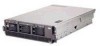
Ethernet activity LEDs: When these LEDs (one for the Remote Supervisor Adapter II, two for the network) are lit, they indicate that activity is taking place on the related network. The following illustration shows the connectors on the rear of the server. Remote Supervisor Adapter II ASM Remote Supervisor Adapter II USB Power-supply connector SCSI AC AC Remote Supervisor Adapter II Ethernet ( RJ-45) 1 2 3 4 5 6 RXE Management port Serial Keyboard Mouse RXE Expansion port Remote Supervisor Adapter II video Ethernet 2 USB 2 Ethernet 1 USB 1 Remote Supervisor Adapter II ASM connector: Attach an ASM breakout cable to this connector to enable system management through the serial connectors and through the ASM RS-485 connectors. Remote Supervisor Adapter II USB connector: This connector is not available for use. Remote Supervisor Adapter II Ethernet connector: Use this connector to connect the Remote Supervisor Adapter II to a network to manage the server from a remote location. To enable remote server management through a network, use the Remote Supervisor Adapter II Ethernet port. To enable remote server management using a modem, use the Remote Supervisor Adapter II serial connector on the breakout cable. To connect the server with another server, use the Remote Supervisor Adapter II ASM interconnect connector. Remote Supervisor Adapter II video connector: Connect the server monitor to this connector. Note: The external power connection on the Remote Supervisor Adapter II is not supported on the xSeries 365 server. Ethernet connectors: Use these connectors to connect the server to a network. USB connectors: Connect USB devices to these connectors. RXE Expansion port: Use this connector to connect the server to a remote I/O enclosure. This port enables the exchange of data between the server and the enclosure (see "RXE Expansion Port connector" on page 64). Mouse connector: Connect a mouse or other pointing device to this connector. Chapter 1. Introduction 7
-
 1
1 -
2
-
3
-
4
-
5
-
6
-
7
-
8
-
9
-
10
-
11
-
 12
12 -
 13
13 -
 14
14 -
 15
15 -
 16
16 -
 17
17 -
 18
18 -
 19
19 -
 20
20 -
 21
21 -
 22
22 -
23
-
24
-
25
-
26
-
27
-
28
-
29
-
30
-
31
-
32
-
33
-
34
-
35
-
36
-
37
-
38
-
39
-
40
-
41
-
42
-
43
-
44
-
45
-
46
-
47
-
48
-
49
-
50
-
51
-
52
-
53
-
54
-
55
-
56
-
57
-
58
-
59
-
60
-
61
-
62
-
63
-
64
-
65
-
66
-
67
-
68
-
69
-
70
-
71
-
72
-
73
-
74
-
75
-
76
-
77
-
78
-
79
-
80
-
81
-
82
-
83
-
84
-
85
-
86
-
87
-
88
-
89
-
90
-
91
-
92
-
93
-
94
-
95
-
96
-
97
-
98
-
99
-
100
-
101
-
102
-
103
-
104
-
105
-
106
-
107
-
108
-
109
-
110
-
111
-
112
-
113
-
114
-
115
-
116
-
117
-
118
-
119
-
120
-
121
-
122
-
123
-
124
-
125
-
126
-
127
-
128
-
129
-
130
-
131
-
132
-
133
-
134
-
135
-
136
-
137
-
138
-
139
-
140
-
141
-
142
-
143
-
144
-
145
-
146
-
147
-
148
-
149
-
150
-
151
-
152
-
153
-
154
-
155
-
156
-
157
-
158
-
159
-
160
-
161
-
162
-
163
-
164
-
165
-
166
-
167
-
168
-
169
-
170
-
171
-
172
-
173
-
174
-
175
-
176
-
177
-
178
-
179
-
180
-
181
-
182
-
183
-
184
-
185
-
186
-
187
-
188
-
189
-
190
-
191
-
192
-
193
-
194
-
195
-
196
-
197
-
198
-
199
-
200
-
201
-
202
-
203
-
204
-
205
-
206
-
207
-
208
-
209
-
210
-
211
-
212
 |
 |
