IBM 88614RX Maintenance Manual - Page 62
Connect one end of the power cord for the new power supply into the connector
 |
UPC - 000435172662
View all IBM 88614RX manuals
Add to My Manuals
Save this manual to your list of manuals |
Page 62 highlights
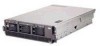
Locking handle (open) Locking latch DCAC Power supply 2 (PS2) AC power connector cover Power supply 1 (PS1) DCAC AC power LED (green) AC DC DC power LED (green) Fan LED (amber) Complete the following steps to install a hot-swap power supply: 1. Read "Safety information" on page 147 and "Installation guidelines" on page 29. 2. Remove the cover (see "Removing the cover and bezel" on page 32). 3. If you are adding a power supply to an empty power bay, remove the cover from the ac power connector opening on the rear of the server. 4. If you are replacing a failed power supply, remove the failed power supply from the bay. a. Unplug the power cord from the connector on the back of the failed power supply. b. Press the locking latch on the power supply handle and move the locking handle to the open position. c. Lift the failed power supply out of the bay. 5. Raise the power supply handle to the open position. 6. Place the new power supply into the power bay in the chassis and fully close the locking handle. 7. Connect one end of the power cord for the new power supply into the connector on the back of the power supply; route the power cord through the cable-management arm and connect the other end of the power cord into a properly grounded electrical outlet. 8. Make sure that the ac power LED on the rear of the power supply and the ac power LED on the top of the power supply are lit, indicating that the power supply is operating correctly. If the server is turned on, make sure that the dc power LED on the top of the power supply is lit also. 9. Continue with "Completing the installation" on page 58. 52 IBM xSeries 365 Types 8861, 8862: Hardware Maintenance Manual and Troubleshooting Guide
-
 1
1 -
2
-
3
-
4
-
5
-
6
-
7
-
8
-
9
-
10
-
11
-
12
-
13
-
14
-
15
-
16
-
17
-
18
-
19
-
20
-
21
-
22
-
23
-
24
-
25
-
26
-
27
-
28
-
29
-
30
-
31
-
32
-
33
-
34
-
35
-
36
-
37
-
38
-
39
-
40
-
41
-
42
-
43
-
44
-
45
-
46
-
47
-
48
-
49
-
50
-
51
-
52
-
53
-
54
-
55
-
56
-
 57
57 -
 58
58 -
 59
59 -
 60
60 -
 61
61 -
 62
62 -
 63
63 -
 64
64 -
 65
65 -
 66
66 -
 67
67 -
68
-
69
-
70
-
71
-
72
-
73
-
74
-
75
-
76
-
77
-
78
-
79
-
80
-
81
-
82
-
83
-
84
-
85
-
86
-
87
-
88
-
89
-
90
-
91
-
92
-
93
-
94
-
95
-
96
-
97
-
98
-
99
-
100
-
101
-
102
-
103
-
104
-
105
-
106
-
107
-
108
-
109
-
110
-
111
-
112
-
113
-
114
-
115
-
116
-
117
-
118
-
119
-
120
-
121
-
122
-
123
-
124
-
125
-
126
-
127
-
128
-
129
-
130
-
131
-
132
-
133
-
134
-
135
-
136
-
137
-
138
-
139
-
140
-
141
-
142
-
143
-
144
-
145
-
146
-
147
-
148
-
149
-
150
-
151
-
152
-
153
-
154
-
155
-
156
-
157
-
158
-
159
-
160
-
161
-
162
-
163
-
164
-
165
-
166
-
167
-
168
-
169
-
170
-
171
-
172
-
173
-
174
-
175
-
176
-
177
-
178
-
179
-
180
-
181
-
182
-
183
-
184
-
185
-
186
-
187
-
188
-
189
-
190
-
191
-
192
-
193
-
194
-
195
-
196
-
197
-
198
-
199
-
200
-
201
-
202
-
203
-
204
-
205
-
206
-
207
-
208
-
209
-
210
-
211
-
212
 |
 |
