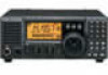
Icom IC-718 Instruction Manual - Page 10
Microphone HM-36
 |
View all Icom IC-718 manuals
Add to My Manuals
Save this manual to your list of manuals |
Page 10 highlights
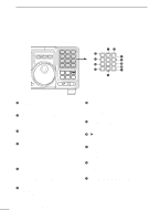
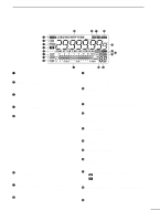
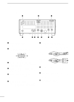
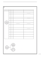
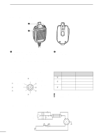
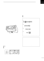
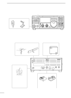
2 PANEL DESCRIPTION s Microphone (HM-36) q w q UP/DOWN SWITCHES [UP]/[DN] Change the selected readout frequency or memory channel. • Continuous pushing changes the frequency or memory channel number continuously. • The [UP]/[DN] switch can simulate a key paddle. Preset in the CW PADDL in initial set mode. (p. 31) w PTT SWITCH Push and hold to transmit; release to receive. • MICROPHONE CONNECTOR (Front view) q Microphone input w +8 V DC output e Frequency up/down i Main readout AF output (varies with [AF]/[BAL]) u GND (Microphone ground) y GND (PTT ground) t PTT r Main readout squelch switch [MIC] PIN NO. w FUNCTION +8 V DC output Frequency up e Frequency down Squelch open r Squelch closed DESCRIPTION Max. 10 mA Ground Ground through 470 Ω "LOW" level "HIGH" level CAUTION: DO NOT short pin 2 to ground as this can damage the internal 8 V regulator. • HM-36 SCHEMATIC DIAGRAM MICROPHONE MICROPHONE CABLE MICROPHONE PLUG MIC ELEMENT + 10µ 2k 4700p + 0.33µ 4700p DOWN UP qu wiy ert PTT RECEIVE 470 TRANSMIT 8
-
 1
1 -
2
-
3
-
4
-
 5
5 -
 6
6 -
 7
7 -
 8
8 -
 9
9 -
 10
10 -
 11
11 -
 12
12 -
 13
13 -
 14
14 -
 15
15 -
16
-
17
-
18
-
19
-
20
-
21
-
22
-
23
-
24
-
25
-
26
-
27
-
28
-
29
-
30
-
31
-
32
-
33
-
34
-
35
-
36
-
37
-
38
-
39
-
40
-
41
-
42
-
43
-
44
-
45
-
46
-
47
-
48
-
49
-
50
-
51
-
52
-
53
-
54
-
55
-
56
-
57
-
58
-
59
-
60
-
61
-
62
 |
 |
