Icom IC-718 Instruction Manual - Page 3

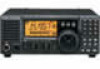
Supplied Accessories - transceiver

Page 3 highlights

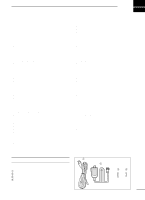
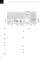
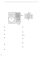
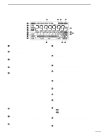
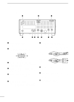
1 TABLE OF CONTENTS IMPORTANT i EXPLICIT DEFINITIONS i PRECAUTIONS i 1 TABLE OF CONTENTS 1 SUPPLIED ACCESSORIES 1 2 PANEL DESCRIPTION 2 - 8 s Front panel 2 s Function display 5 s Rear panel 6 s Microphone (HM-36 8 3 INSTALLATION AND CONNECTIONS ......... 9 - 14 s Unpacking 9 s Selecting a location 9 s Grounding 9 s Antenna connection 9 s Required connections 10 s Advanced connections 11 s Power supply connections 12 s Liner amplifier connections 13 s External antenna tuners 14 4 FREQUENCY SETTING 15 - 19 s When first applying power 15 s Initial setting 15 s VFO description 16 s Frequency setting 17 s Dial lock function 19 5 RECEIVE AND TRANSMIT 20 - 34 s Mode selection 20 s Squelch and RF gain 20 s Function for receive 21 s DSP function (option 23 s Filter selection 24 s Filter setting 25 s Function for transmit 26 s Split frequency operation 30 s SWR 30 s Function for CW 31 s Function for RTTY 33 6 MEMORY OPERATION 35 - 38 s Memory channels 35 s Memory channel selection 35 s Memory channel programming 36 s Frequency transferring 37 s Memory clearing 38 7 SCANS 39 - 40 s Scan types 39 s Preparation 39 s Programmed scan operation 40 s Memory scan operation 40 8 SET MODE 41 - 47 s General 41 s Quick set mode items 42-43 s Initial set mode items 44-47 9 INSTALLATION AND CONNECTIONS ....... 48 - 51 s Opening the transceiver's case 48 s Optional bracket and carrying handle 48 s CR-338 HIGH STABILITY CRYSTAL UNIT .......... 49 s UT-102 VOICE SYNTHESIZER UNIT 49 s UT-106 DSP RECEIVE UNIT 50 s Optional IF filters 50 s AT-180 internal switch description 51 10 MAINTENANCE 52 - 53 s Troubleshooting 52 s Fuse replacement 53 s Resetting the CPU 53 11 SPECIFICATIONS 54 12 OPTIONS 55 - 56 13 CONTROL COMMAND 57 - 58 s Remote jack (CI-V) information 57 14 INTERNAL VIEWS 59 s Top view 59 s Bottom view 59 SUPPLIED ACCESSORIES q w The transceiver comes with the following accessories. Qty. q DC power cable 1 w Hand microphone (HM-36 1 e Fuse (FGB 20 A; for DC cable 1 r Fuse (FGB 4 A; internal use 1 er 1

  • 1
  • 2
  • 3
  • 4
  • 5
  • 6
  • 7
  • 8
  • 9
  • 10
  • 11
  • 12
  • 13
  • 14
  • 15
  • 16
  • 17
  • 18
  • 19
  • 20
  • 21
  • 22
  • 23
  • 24
  • 25
  • 26
  • 27
  • 28
  • 29
  • 30
  • 31
  • 32
  • 33
  • 34
  • 35
  • 36
  • 37
  • 38
  • 39
  • 40
  • 41
  • 42
  • 43
  • 44
  • 45
  • 46
  • 47
  • 48
  • 49
  • 50
  • 51
  • 52
  • 53
  • 54
  • 55
  • 56
  • 57
  • 58
  • 59
  • 60
  • 61
  • 62

1
1
TABLE OF CONTENTS
The transceiver comes with the following accessories.
Qty.
q
DC power cable
....................................................
1
w
Hand microphone (HM-36)
..................................
1
e
Fuse (FGB 20 A; for DC cable)
............................
1
r
Fuse (FGB 4 A; internal use)
...............................
1
SUPPLIED ACCESSORIES
q
w
e
r
IMPORTANT
..............................................................
i
EXPLICIT DEFINITIONS
...........................................
i
PRECAUTIONS
.........................................................
i
1
TABLE OF CONTENTS
.......................................
1
SUPPLIED ACCESSORIES
.....................................
1
2
PANEL DESCRIPTION
...................................
2–8
Front panel
........................................................
2
Function display
.................................................
5
Rear panel
.........................................................
6
Microphone (HM-36)
.........................................
8
3
INSTALLATION AND CONNECTIONS
.........
9–14
Unpacking
..........................................................
9
Selecting a location
...........................................
9
Grounding
..........................................................
9
Antenna connection
...........................................
9
Required connections
......................................
10
Advanced connections
....................................
11
Power supply connections
...............................
12
Liner amplifier connections
..............................
13
External antenna tuners
..................................
14
4
FREQUENCY SETTING
..............................
15–19
When first applying power
...............................
15
Initial setting
....................................................
15
VFO description
...............................................
16
Frequency setting
............................................
17
Dial lock function
.............................................
19
5
RECEIVE AND TRANSMIT
.........................
20–34
Mode selection
................................................
20
Squelch and RF gain
.......................................
20
Function for receive
.........................................
21
DSP function (option)
......................................
23
Filter selection
.................................................
24
Filter setting
.....................................................
25
Function for transmit
........................................
26
Split frequency operation
.................................
30
SWR
................................................................
30
Function for CW
...............................................
31
Function for RTTY
...........................................
33
6
MEMORY OPERATION
...............................
35–38
Memory channels
............................................
35
Memory channel selection
...............................
35
Memory channel programming
........................
36
Frequency transferring
....................................
37
Memory clearing
..............................................
38
7 SCANS
........................................................
39–40
Scan types
.......................................................
39
Preparation
......................................................
39
Programmed scan operation
...........................
40
Memory scan operation
...................................
40
8
SET MODE
..................................................
41–47
General
............................................................
41
Quick set mode items
.................................
42-43
Initial set mode items
.................................
44-47
9
INSTALLATION AND CONNECTIONS
.......
48–51
Opening the transceiver’s case
.......................
48
Optional bracket and carrying handle
...............
48
CR-338
HIGH STABILITY CRYSTAL UNIT
..........
49
UT-102
VOICE SYNTHESIZER UNIT
..................
49
UT-106
DSP RECEIVE UNIT
..............................
50
Optional IF filters
.............................................
50
AT-180 internal switch description
...................
51
10 MAINTENANCE
........................................
52–53
Troubleshooting
...............................................
52
Fuse replacement
............................................
53
Resetting the CPU
...........................................
53
11 SPECIFICATIONS
...........................................
54
12 OPTIONS
..................................................
55–56
13
CONTROL COMMAND
............................
57–58
Remote jack (CI-V) information
.......................
57
14
INTERNAL VIEWS
...........................................
59
Top view
...........................................................
59
Bottom view
.....................................................
59