Icom IC-718 Instruction Manual - Page 54
Maintenance - service manual
 |
View all Icom IC-718 manuals
Add to My Manuals
Save this manual to your list of manuals |
Page 54 highlights
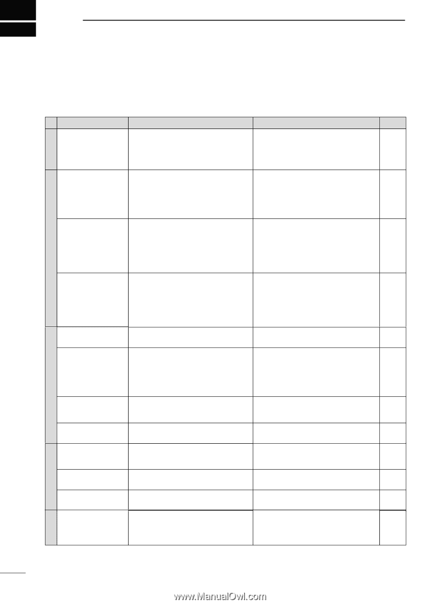
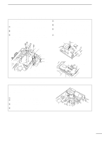
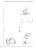
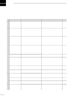
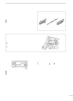
10 MAINTENANCE s Troubleshooting The following chart is designed to help you correct problems which are equipment malfunctions. If you are not able to locate the cause of a problem or solve it through the use of this chart, contact your nearest Icom Dealer or Service Center. POWER PROBLEM POSSIBLE CAUSE Power does not come on • DC power cable is improperly connected. when the [POWER] switch • Fuse is blown. is pushed. • Power Supply not turned ON. SOLUTION REF. • Reconnect the DC power cable correctly. • Check for the cause, then replace the fuse with a spare one. (Fuses are installed in the DC power cable and the internal PA unit.) p. 12 p. 53 No sound comes from the • Volume level is too low. • Rotate [AF] clockwise to obtain a suitable p. 2 speaker. listening level. • The squelch is closed. • Rotate [RF/SQL] to 10 o'clock position to open p. 2 the squelch. • The transceiver is in the transmitting condition. • Check the SEND line of an external unit, if p. 6 desired. Sensitivity is low. • The antenna is not connected properly. • The antenna for another band is connected. • The antenna is not properly tuned. • The attenuator is activated. • Reconnect to the antenna connector. • Connect an antenna suitable for the operating frequency. • Push [TUNER] for 2 sec. to manually tune the antenna. • Push [ATT] to select "ATT" OFF. - - p. 3 p. 3 RECEIVE TRANSMIT Receive audio is distorted. • The operating mode is not selected correctly. • IF SHIFT function is activated. • Noise blanker function is activated. • Preamp is activated. • Select a suitable operating mode. • Rotate the SHIFT control to center position. • Push [NB] to turn the function OFF. • Push [P.AMP] to turn the function OFF. p. 20 p. 21 p. 21 p. 22 • The noise reduction is activated and the [NR] • Set the [NR] control for maximum readability. control is set too high. p. 23 Transmitting is impossi- • The operating frequency is not set to a ham • Set the frequency to a ham band. ble. band. p. 17 Output power is too low. • [RF POWER] is set too low. • [MIC GAIN] is set too low. • The antenna for another band is selected. • The antenna is not properly tuned. • Set [RF POWER] to a suitable position. • Set [MIC GAIN] to a suitable position. • Select an antenna suitable for the operating frequency. • Push [TUNER] for 2 sec. to manually tune the antenna. p. 42 p. 42 p. 10 p. 3 No contact possible with • RIT function is activated. another station. • Split frequency function is activated. • Push [RIT] to turn the function OFF. • Push [SPLIT] to turn the function OFF. p. 21 pgs. 7 31, 32 Transmitted signals are • [MIC GAIN] is set too high. distorted. • [COMP] function is activated. Programmed scan does • Squelch is open. not stop. • [RF/SQL] is assigned to RF gain control and squelch is open. • Set [MIC GAIN] to a suitable position. • Turn [COMP] off. • Set [RF/SQL] to the threshold point. • Reset [RF/SQL] control assignment and set it to the threshold point. p. 2 p. 27 p. 3 p. 30 Programmed scan does • The same frequencies have been programmed • Program different frequencies in scan edge p. 40 not start. in scan edge memory channels P1 and P2. memory channels P1 and P2. Memory scan does not • 2 or more memory channels have not been • Program 2 or more memory channels. start. programmed. p. 40 The displayed frequency • The dial lock function is activated. does not change properly. • A quick set mode screen is selected. • The internal CPU has malfunctioned. • Push [LOCK] to deactivate the function. • Push [SET] to exit the quick set mode. • Reset the CPU. p. 6 p. 41 p. 53 SCAN DISPLAY 52
-
 1
1 -
2
-
3
-
4
-
5
-
6
-
7
-
8
-
9
-
10
-
11
-
12
-
13
-
14
-
15
-
16
-
17
-
18
-
19
-
20
-
21
-
22
-
23
-
24
-
25
-
26
-
27
-
28
-
29
-
30
-
31
-
32
-
33
-
34
-
35
-
36
-
37
-
38
-
39
-
40
-
41
-
42
-
43
-
44
-
45
-
46
-
47
-
48
-
 49
49 -
 50
50 -
 51
51 -
 52
52 -
 53
53 -
 54
54 -
 55
55 -
 56
56 -
 57
57 -
 58
58 -
 59
59 -
60
-
61
-
62
 |
 |