Icom IC-718 Instruction Manual - Page 20
Band selection, Programmable tuning steps, Band stacking resister
 |
View all Icom IC-718 manuals
Add to My Manuals
Save this manual to your list of manuals |
Page 20 highlights
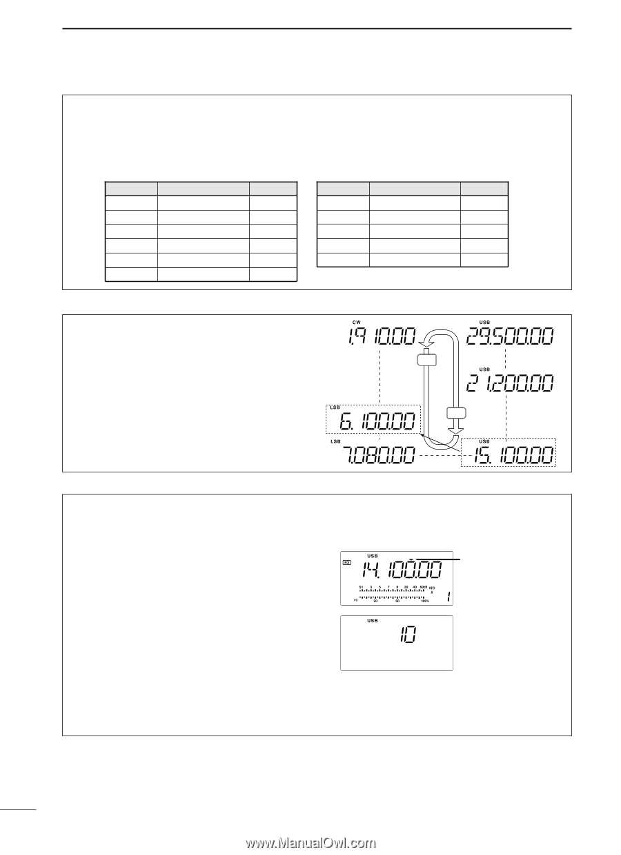
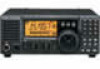
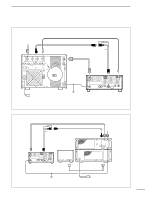
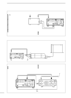
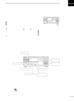
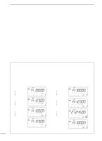
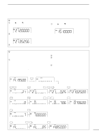
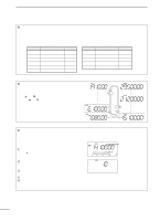
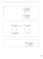
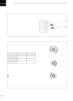
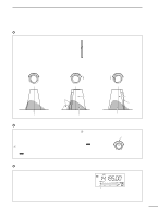
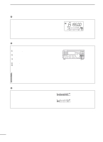
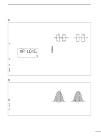
4 FREQUENCY SETTING D Band stacking resister The band stacking register automatically stores the last frequency and mode used for each band. This is convenient for contest operation, etc. The tables below shows the band stacking register default settings for each band. BAND 1.9 MHz 3.5 MHz 7 MHz 10 MHz 14 MHz General BAND 1.91000 MHz 3.55000 MHz 7.05000 MHz 10.12000 MHz 14.10000 MHz 15.10000 MHz BAND CW LSB LSB CW USB USB BAND 18 MHz 21 MHz 24 MHz 28 MHz 29 MHz BAND 18.10000 MHz 21.20000 MHz 24.95000 MHz 28.50000 MHz 29.50000 MHz BAND USB USB USB USB USB D Band selection All HF ham bands and a general coverage receiver band are included in the IC-718. Push [∫ UP]/[√ DN] to select the desired band. • Pushing [∫ UP]/[√ DN] continuously scrolls through the available bands. Note: For example, if 6.10000 MHz is resistered as the General coverage frequency, then the General coverage band automatically positions itself between 3.5 MHz and 7 MHz band. General (new) D Programmable tuning steps Programmable tuning steps are available to suit your operating requirements. These tuning steps are: • Selectable from 0.1, 1, 5, 9, 10, 100 kHz q Push [TS], the programmable tuning step indicator, ""," then appears above the 1 kHz. • Rotating the tuning dial changes the frequency according to the set tuning step. w Push [TS] for 2 sec. while the programmable tuning step indicator appears to enter the tuning step set mode. e Rotate the tuning dial to set the desired tuning step. r Push [TS] to exit the tuning step set mode. t Rotate the tuning dial to change the frequency ac- cording to the set tuning step. √ DN UP ∫ General (old) Programmable tuning step indicator 10 KHz tuning steps is selected. 18
-
 1
1 -
2
-
3
-
4
-
5
-
6
-
7
-
8
-
9
-
10
-
11
-
12
-
13
-
14
-
 15
15 -
 16
16 -
 17
17 -
 18
18 -
 19
19 -
 20
20 -
 21
21 -
 22
22 -
 23
23 -
 24
24 -
 25
25 -
26
-
27
-
28
-
29
-
30
-
31
-
32
-
33
-
34
-
35
-
36
-
37
-
38
-
39
-
40
-
41
-
42
-
43
-
44
-
45
-
46
-
47
-
48
-
49
-
50
-
51
-
52
-
53
-
54
-
55
-
56
-
57
-
58
-
59
-
60
-
61
-
62
 |
 |