Icom IC-718 Instruction Manual - Page 12
Required connections - microphone
 |
View all Icom IC-718 manuals
Add to My Manuals
Save this manual to your list of manuals |
Page 12 highlights
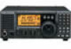
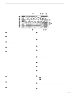
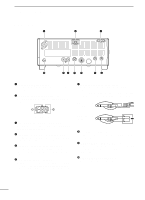
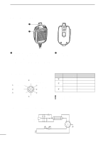
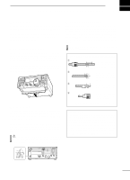
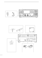
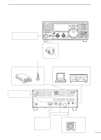
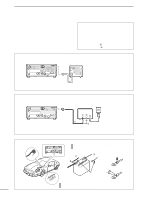
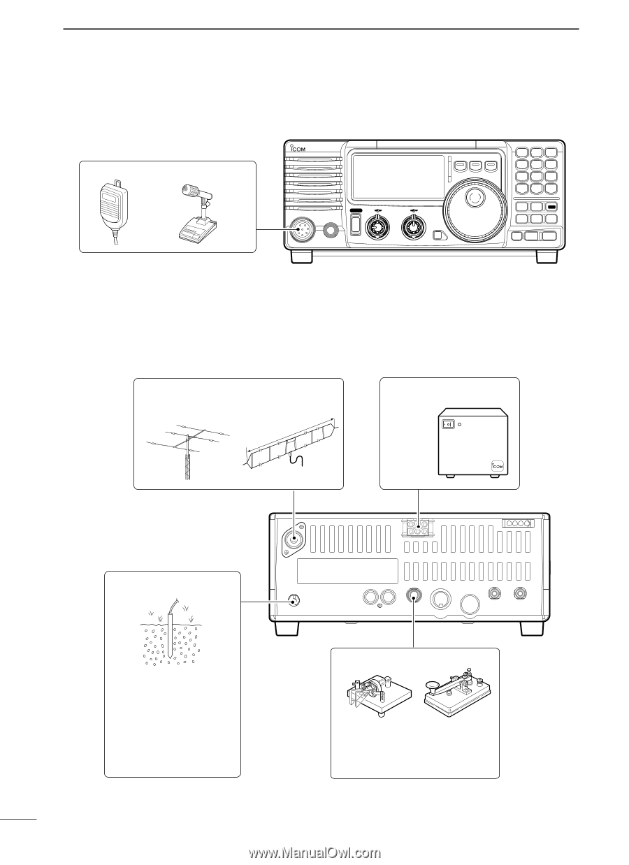
3 INSTALLATION AND CONNECTIONS s Required connections • Front panel MICROPHONES (p. 55) HM-36 SM-20 IC-718 MODE FIL TS PWR AF RF/SQL RIT SHIFT MIC PHONES LOCK 1 2 3 V/M A=B A/B 4 5 6 MW M - CL ˛ M V 7 8 9 SPL SCN VOX . 0 NR ANF F-INP ENT NB COMP SET P.AMP ATT TUNER ∫ CH DN UP √ • Rear panel ANTENNA (p. 56) [Example]: 1.8-30 MHz bands AH-710 approx. 24.5 m; 80.3 ft DC POWER SUPPLY PS-85 GROUND (p. 9) Use the heaviest gauge wire or strap available and make the connection as short as possible. Grounding prevents electrical shocks, TVI and other problems. 10 CW KEY A straight key can be used when the internal electronic keyer is turned OFF in "CW PADDL" in initial set mode. (p. 31)
-
 1
1 -
2
-
3
-
4
-
5
-
6
-
 7
7 -
 8
8 -
 9
9 -
 10
10 -
 11
11 -
 12
12 -
 13
13 -
 14
14 -
 15
15 -
 16
16 -
 17
17 -
18
-
19
-
20
-
21
-
22
-
23
-
24
-
25
-
26
-
27
-
28
-
29
-
30
-
31
-
32
-
33
-
34
-
35
-
36
-
37
-
38
-
39
-
40
-
41
-
42
-
43
-
44
-
45
-
46
-
47
-
48
-
49
-
50
-
51
-
52
-
53
-
54
-
55
-
56
-
57
-
58
-
59
-
60
-
61
-
62
 |
 |
10
3
INSTALLATION AND CONNECTIONS
■
Required connections
MIC
I
C-
718
PHONES
RF/SQL
AF
SHIFT
RIT
LOCK
MODE
FIL
TS
PWR
TUNER
√
∫
COMP
P.AMP
UP
NB
ATT
SET
CH
DN
ENT
F-INP
V/M
1
MW
4
A=B
2
M-CL
5
SCN
8
ANF
0
NR
.
A/B
3
VOX
9
7
SPL
M V
6
▲
�
MICROPHONES
(p. 55)
SM-20
HM-36
GROUND
(p. 9)
Use the heaviest gauge wire
or strap available and make
the connection as short as
possible.
Grounding prevents electrical
shocks,
TVI
and
other
problems.
ANTENNA
(p. 56)
[Example]: 1.8–30 MHz bands
DC POWER SUPPLY
PS-85
CW KEY
A straight key can be used when the
internal electronic keyer is turned
OFF in “CW PADDL” in initial
set
mode. (p. 31)
approx. 24.5 m; 80.3 ft
AH-710
•Front panel
•Rear panel