Icom IC-718 Instruction Manual - Page 16
External antenna tuners - hf
 |
View all Icom IC-718 manuals
Add to My Manuals
Save this manual to your list of manuals |
Page 16 highlights
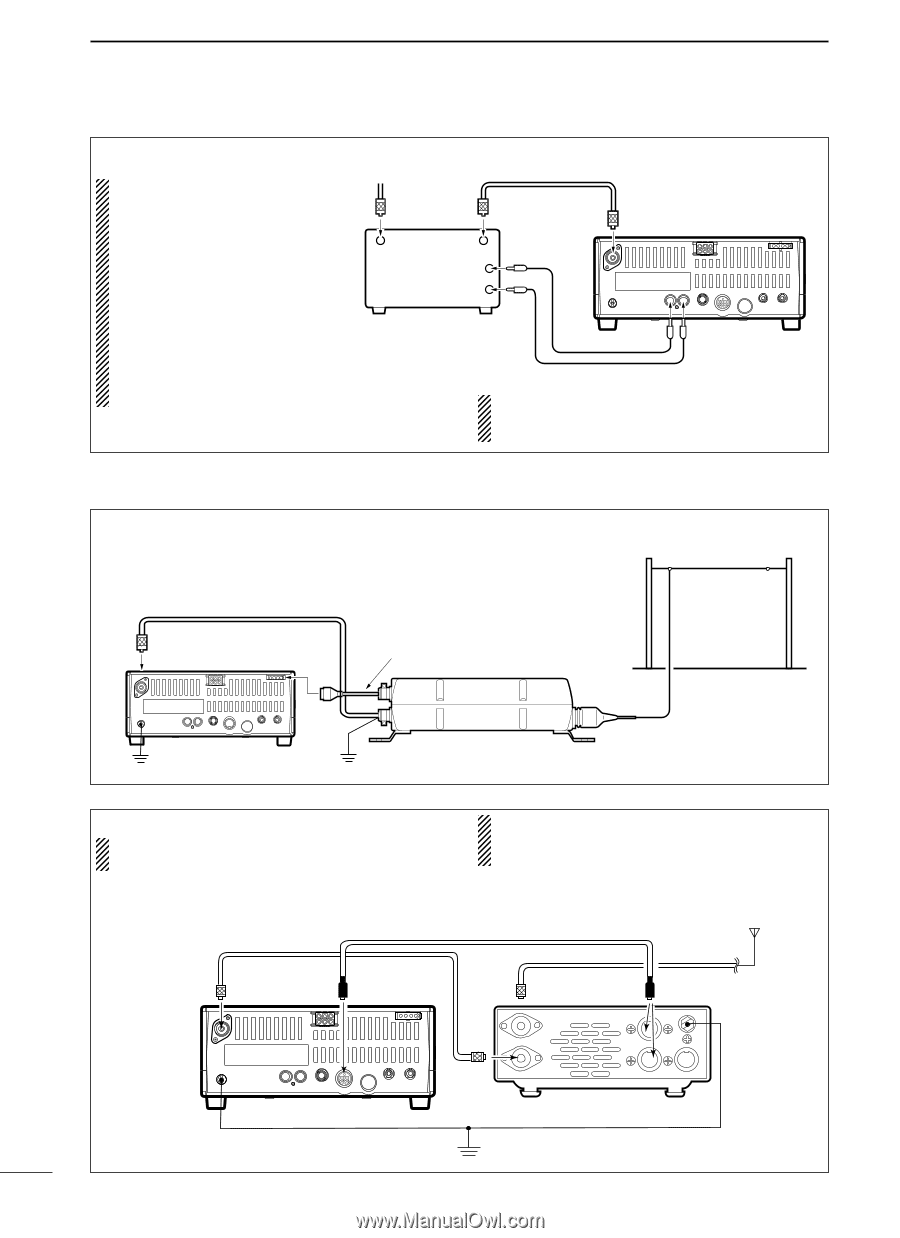
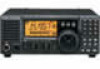
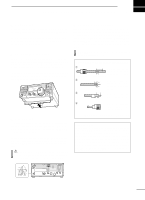
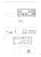
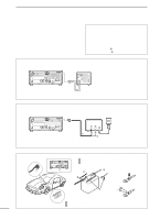
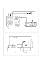
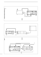
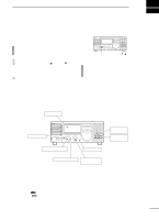
3 INSTALLATION AND CONNECTIONS CONNECTING A NON-ICOM LINER AMPLIFIER R WARNING: Set the transceiver output power and linear amplifier ALC output level referring to the linear amplifier instruction manual. The ALC input level must be in the range 0 V to -4 V, and the transceiver does not accept positive voltage. Nonmatched ALC and RF power settings could cause a fire or ruin the linear amplifier. To an antenna RF OUTPUT RF INPUT SEND ALC Non-Icom linear amplifier 50 Ω coaxial cable ANT IC-718 SEND 13 9 10 11 12 5678 1234 ALC The specifications for the SEND relay are 16 V DC 2 A. If this level is exceeded, a large external relay must be used. s External antenna tuners CONNECTING THE AH-4 (p. 29) Long wire or optional AH-2b Coaxial cable (from the AH-4) Control cable IC-718 Ground Ground AH-4 CONNECTING THE AT-180 (p. 28) DO NOT! connect AT-180 and AH-4 at the same time. Both tuners will not function correctly. Turn the IC-718's power OFF when connecting the AT-180, otherwise, the CPU may malfunction and the AT-180 may not function properly. Coaxial cable supplied with the AT-180 [ANT] ACC cable supplied with the AT-180 [ACC] one of two AT-180 [ACC] connectors HF antenna IC-718 13 9 10 11 12 5678 1234 Ground 14
-
 1
1 -
2
-
3
-
4
-
5
-
6
-
7
-
8
-
9
-
10
-
 11
11 -
 12
12 -
 13
13 -
 14
14 -
 15
15 -
 16
16 -
 17
17 -
 18
18 -
 19
19 -
 20
20 -
 21
21 -
22
-
23
-
24
-
25
-
26
-
27
-
28
-
29
-
30
-
31
-
32
-
33
-
34
-
35
-
36
-
37
-
38
-
39
-
40
-
41
-
42
-
43
-
44
-
45
-
46
-
47
-
48
-
49
-
50
-
51
-
52
-
53
-
54
-
55
-
56
-
57
-
58
-
59
-
60
-
61
-
62
 |
 |