Icom IC-718 Instruction Manual - Page 51
CR-338, UT-102
 |
View all Icom IC-718 manuals
Add to My Manuals
Save this manual to your list of manuals |
Page 51 highlights
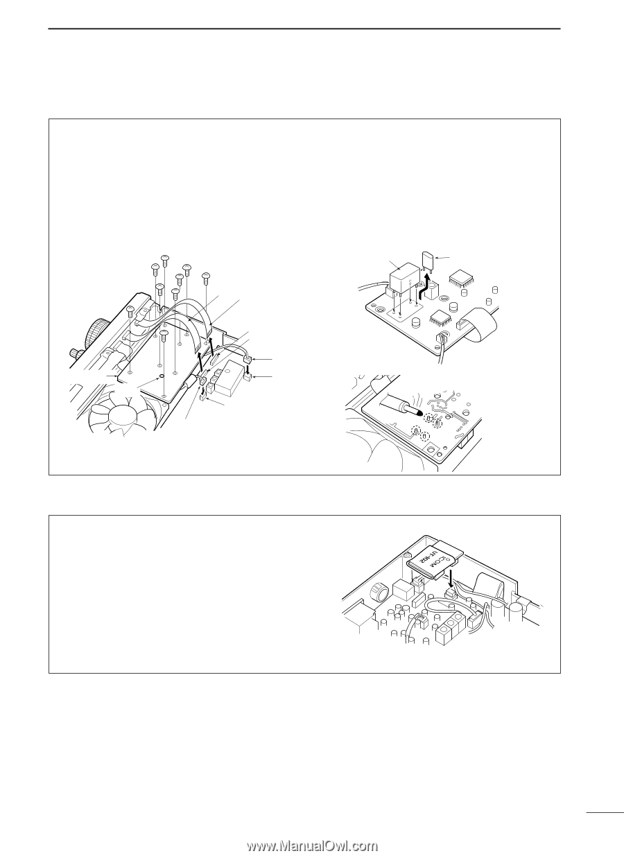
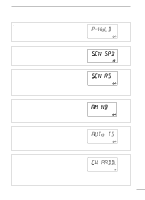
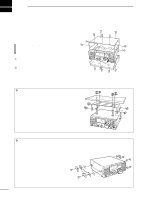
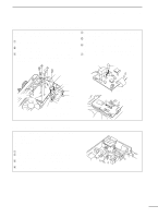
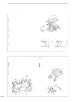
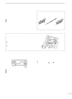
9 INSTALLATION AND CONNECTIONS s CR-338 HIGH STABILITY CRYSTAL UNIT By installing the CR-338, the total frequency stability of the receiver will be improved. q Remove the bottom cover as shown in the diagram before. w Disconnect W2 from J4401 (MAIN unit) and W3 from J4201 (MAIN unit). e Remove 9 screws from the PLL unit, disconnect P4 from J201 (MAIN unit) and P2 from J401 (MAIN unit), then remove the PLL unit. r Remove the supplied internal crystal and replace with the CR-338. t Return the PLL unit, plugs and flat cables to their original positions. y Adjust the reference frequency at C16 using a frequency counter if desired. • Connect the frequency counter to P. 2 (PLL unit). u Return the bottom cover to its original position. CR-338 Internal crystal PLL unit C 16 W 2 W 3 J 4201 J 4401 P 4 J 201 J 401 MAIN unit P 2; Frequency check point (Connect a frequency counter and adjust the frequency to 64.00000 MHz with C 16.) PLL unit Solder 4 leads s UT-102 VOICE SYNTHESIZER UNIT The UT-102 announces the received frequency, mode, S-meter level and current time in a clear, electronically-generated voice, in English (or Japanese). ➥ Push [LOCK] for 1 sec. to announce the frequency, etc. q Remove the bottom cover as shown above. w Remove the protective paper attached to the bot- tom of the UT-102 to expose the adhesive strip. e Plug UT-102 into J2501 on the MAIN unit as shown at right. r Return the bottom cover to its original position. 49
-
 1
1 -
2
-
3
-
4
-
5
-
6
-
7
-
8
-
9
-
10
-
11
-
12
-
13
-
14
-
15
-
16
-
17
-
18
-
19
-
20
-
21
-
22
-
23
-
24
-
25
-
26
-
27
-
28
-
29
-
30
-
31
-
32
-
33
-
34
-
35
-
36
-
37
-
38
-
39
-
40
-
41
-
42
-
43
-
44
-
45
-
 46
46 -
 47
47 -
 48
48 -
 49
49 -
 50
50 -
 51
51 -
 52
52 -
 53
53 -
 54
54 -
 55
55 -
 56
56 -
57
-
58
-
59
-
60
-
61
-
62
 |
 |