Icom IC-718 Instruction Manual - Page 52
UT-106, Optional IF filters - dsp unit
 |
View all Icom IC-718 manuals
Add to My Manuals
Save this manual to your list of manuals |
Page 52 highlights
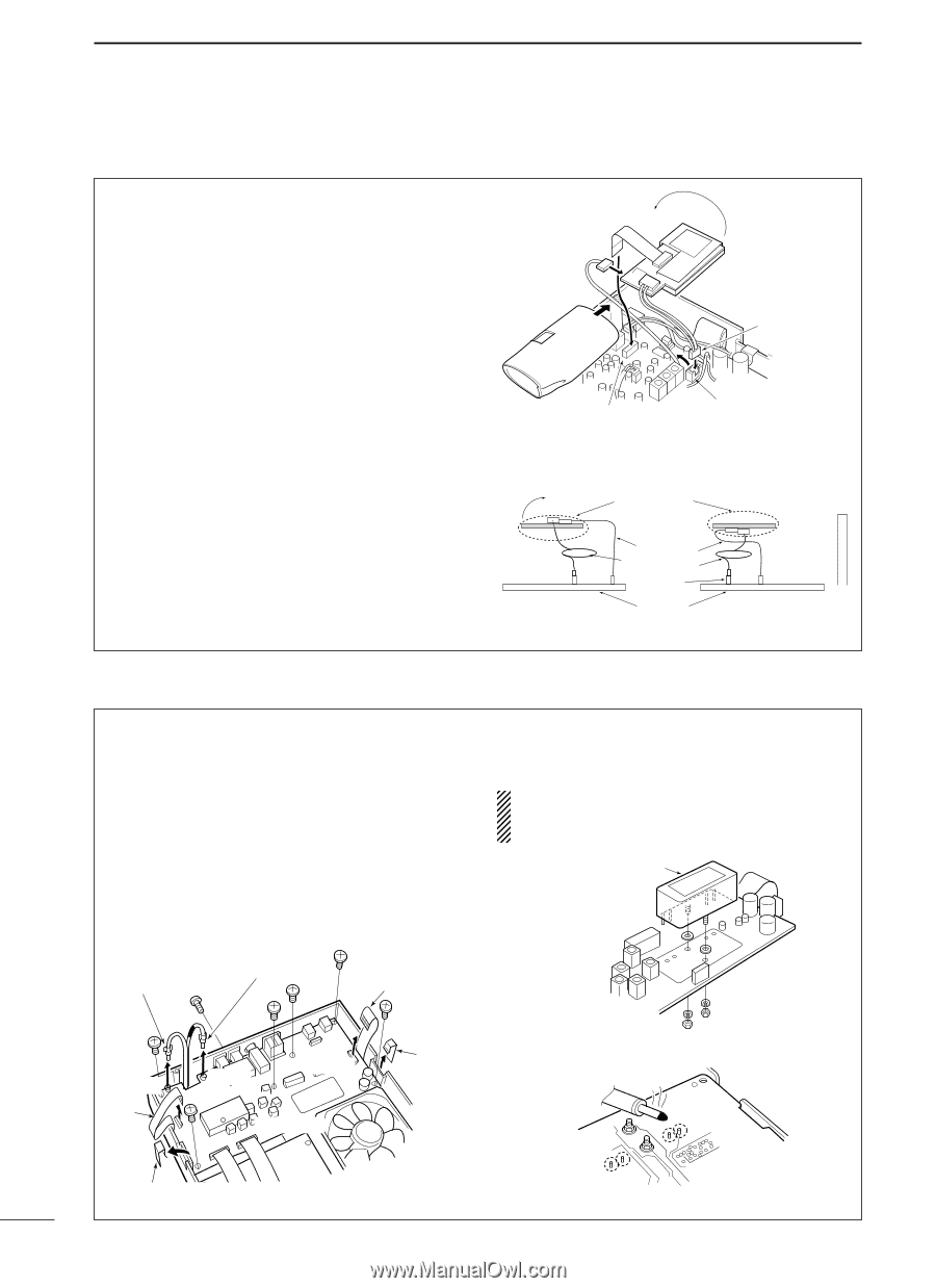
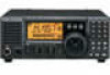
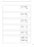
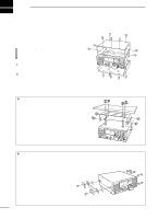
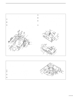
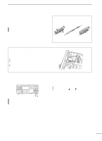
9 INSTALLATION AND CONNECTIONS s UT-106 DSP RECEIVE UNIT The UT-106 provides AF DSP functions such as noise reduction and auto notch. q Remove the bottom cover. w Slide the insulating case onto the UT-106 as shown right. (Fig. 1) e Remove the connection cable (P2601) from J2602 on the MAIN unit. Connect the cable into J1 on the UT-106. r Plug the connection cable (P1) from the UT-106 to J2602 on the MAIN unit. t Plug the flat cable into J3 on the UT-106 and to J2603 on the MAIN unit. • Take care regarding the conductor direction. y Turn the UT-106 unit over. (Fig. 2) • No need to fix with an adhesive strip, etc. u Put the UT-106 on the MAIN unit. • No need to fix with an adhesive strip, etc. • Ensure that the surplus cable from UT-106 is stored under the unit. i Return the bottom cover to its original position. flat cable P 2601 Turn the unit over UT-106 P 1 (from UT-106) insulating case J 2603 • Turn the unit over J 2602 MAIN unit Fig. 1 UT-106 J 2602 Fig. 2 insulating case " Flat cable* Surplus cable J 2602 Rear panel UT-106 J 2603 Main unit * Supplied with UT-106 s Optional IF filters Several IF filters are available for the IC-718. You can install 1 filter for 455 KHz IF. Choose the appropriate filter for your operating needs. (pgs, 24-25) D Installation q Remove the bottom cover as shown on the p. 48. w Remove 7 screws, connection cable p1 from J1, p5 from J701, W4 from J4101 and W5 from J4001 and 2 Tr-clampers as shown in the diagram below. e Install the desired 455 KHz filter as shown in the diagram below. r Mounting the filter with supplied washers and nuts. P 5 P 1 W 4 t Solder the 4 leads. y Return the MAIN unit and bottom cover to their original positions. After filter installation, specify the installed filter using initial set mode. (p. 47) Otherwise, the installed filter will not function properly. Optional IF filter J 1 W 5 J 701 J 4101 MAIN unit Tr-clamper Solder 4 leads Tr-clamper 50
-
 1
1 -
2
-
3
-
4
-
5
-
6
-
7
-
8
-
9
-
10
-
11
-
12
-
13
-
14
-
15
-
16
-
17
-
18
-
19
-
20
-
21
-
22
-
23
-
24
-
25
-
26
-
27
-
28
-
29
-
30
-
31
-
32
-
33
-
34
-
35
-
36
-
37
-
38
-
39
-
40
-
41
-
42
-
43
-
44
-
45
-
46
-
 47
47 -
 48
48 -
 49
49 -
 50
50 -
 51
51 -
 52
52 -
 53
53 -
 54
54 -
 55
55 -
 56
56 -
 57
57 -
58
-
59
-
60
-
61
-
62
 |
 |