Icom IC-718 Instruction Manual - Page 4
Panel Description - computer control
 |
View all Icom IC-718 manuals
Add to My Manuals
Save this manual to your list of manuals |
Page 4 highlights
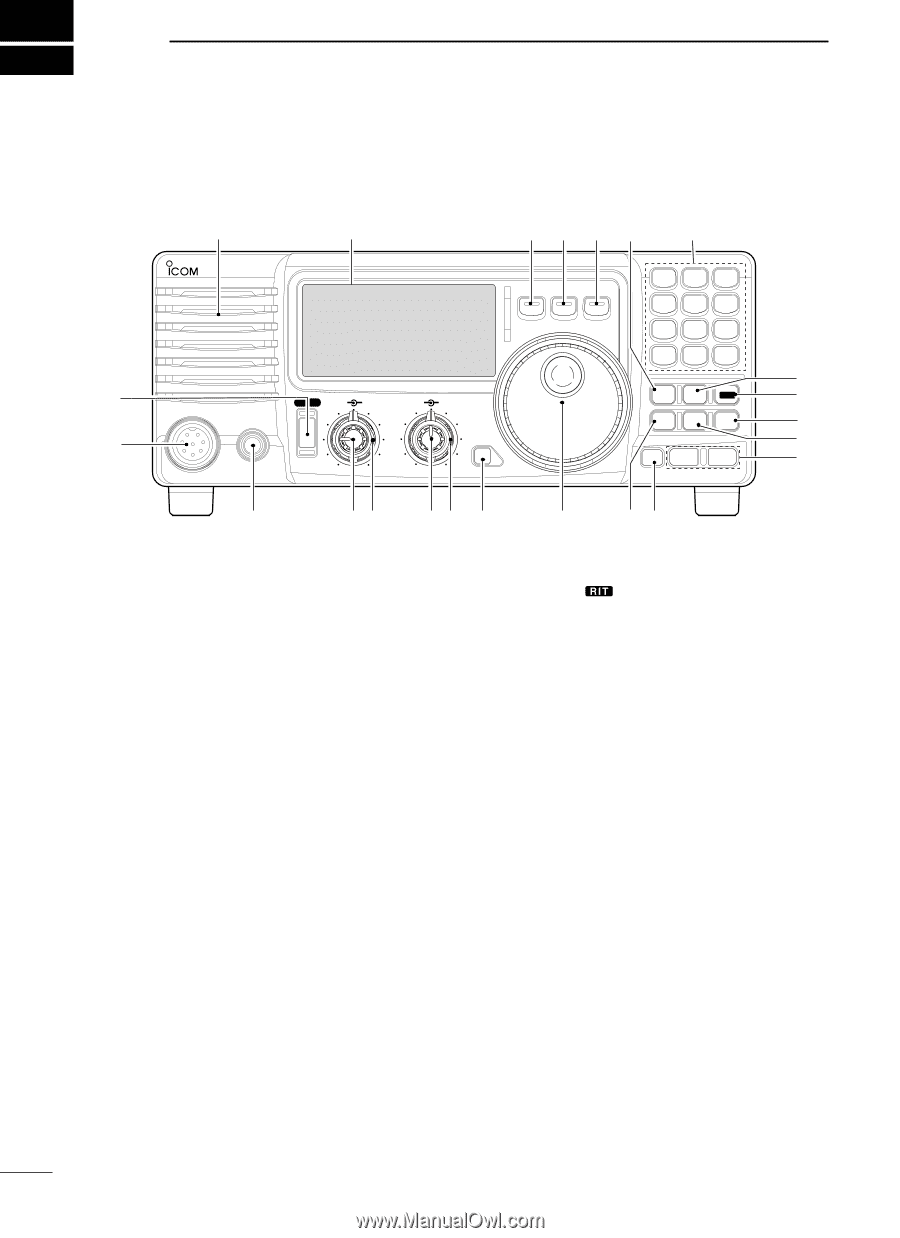
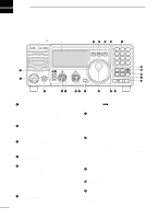
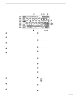
2 PANEL DESCRIPTION s Front panel Speaker Function Display @1 @0 !9 !8 !7 IC-718 MODE FIL TS 1 2 3 V/M A=B A/B 4 5 6 MW M -CL ˛ M V q PWR AF RF/SQL RIT SHIFT MIC PHONES w LOCK 7 8 9 SPL SCN VOX . 0 NR ANF F-INP ENT !6 NB COMP SET !5 P.AMP ATT TUNER !4 !3 CH √ DN UP ∫ !2 e rt yu i o !0 !1 or rotate the control counterclockwise to decrease the q POWER SWITCH [PWR] ➥ Push momentarily to turn power ON. frequency. " " appears on the display. • The shift frequency range is ±1.2 kHz. • Turn the optional DC power supply ON in advance. ➥ Push for 1 sec. to turn power OFF. ➥ While pushing and holding [SET], push [PWR] to u IF SHIFT CONTROLS [SHIFT] (Outer control; p. 21) enter the initial set mode. (p. 41) Shifts the center frequency of the receivers's IF pass-band. w MICROPHONE CONNECTOR [MIC] Accepts supplied or optional microphone. • See p. 55 for appropriate microphones. • Rotate the control colckwise to shift the center frequency higher, or rotate the control counterclockwise to shift the center frequency lower. • See p. 8 for microphone connector information. i LOCK SWITCH [LOCK] (p. 19) e HEADPHONE JACK [PHONES] (p. 11) Accepts headphones (8 Ω). • When headphones are connected, the internal speaker Push momentarily to turn the dial lock function ON and OFF. • The dial lock function electronically locks the main dial. or connected external speaker does not function. • When the optional UT-102 VOICE SYNTHESIZER UNIT is installed (p. 49), push for 1 sec. to have the frequency, r AF CONTROL [AF] (inner control) etc. announced. Varies the audio output level from the speaker. • UT-102 operation can be adjusted in initial set mode (p. 46). t RF GAIN/SQUELCH CONTROL [RF/SQL] (outer control; pgs. 20, 44) o MAIN DIAL Adjusts the squelch threshold level. The squelch re- Changes the displayed frequency, selects quick/ini- moves noise output from the speaker (closed con- tial set mode items, etc. dition) when no signal is received. • The squelch is available for all modes. !0 PREAMP SWITCH [P.AMP] (p. 21) • The control can be set as the squelch plus RF gain controls or squelch control only (RF gain is fixed at maxi- Push momentarily to turn the preamp ON or OFF. mum) in initial set mode. !1 CH SWITCH [CH] (p. 35) y RIT CONTROLS [RIT] (Inner control; p. 21) ➥ Shifts the receive frequency without changing the transmit frequency. • Rotate the control clockwise to incerase the frequency, Push momentarily to turn the memory channel select function ON or OFF. • [MEMO] blinks while memory channel select function is turned on. 2
-
 1
1 -
 2
2 -
 3
3 -
 4
4 -
 5
5 -
 6
6 -
 7
7 -
 8
8 -
 9
9 -
 10
10 -
11
-
12
-
13
-
14
-
15
-
16
-
17
-
18
-
19
-
20
-
21
-
22
-
23
-
24
-
25
-
26
-
27
-
28
-
29
-
30
-
31
-
32
-
33
-
34
-
35
-
36
-
37
-
38
-
39
-
40
-
41
-
42
-
43
-
44
-
45
-
46
-
47
-
48
-
49
-
50
-
51
-
52
-
53
-
54
-
55
-
56
-
57
-
58
-
59
-
60
-
61
-
62
 |
 |