Icom IC-718 Instruction Manual - Page 26
Filter selection - filter fl 52a install
 |
View all Icom IC-718 manuals
Add to My Manuals
Save this manual to your list of manuals |
Page 26 highlights
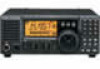
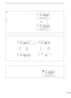
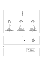
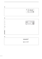
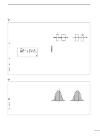
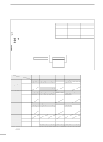
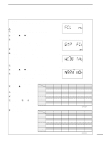
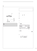
5 RECEIVE AND TRANSMIT s Filter selection The filter selection switches the IF passband width as shown in the table at right. The filter selection is automatically memorized in each mode. q Select the desired mode with the mode switches. w Push [FIL] one or more times to select the desired filter combination. • ã or ç does not appear while in normal IF filter mode. • ç appears when the wide IF filter is selected. • ã appears when the narrow IF filter is selected. • Optional filter variations Name FL-52A FL-53A FL-96 FL-222 FL-257 Band width 500 Hz/-6dB 250 Hz/-6dB 2.8 KHz/-6dB 1.8 KHz/-6dB 3.3 KHz/-6dB Mode CW/RTTY-N CW/RTTY-N SSB-W SSB-N SSB-W When an optional filter is installed, set the optional filter in initial set mode. An optional filter is not selected by default. • Filter construction 2nd IF signal CFWS450HT (6 kHz)*** Through FL-65 (2.4 kHz)* FL-257 (3.3 kHz)** FL-96 (2.8 kHz)** FL-222 (1.8 kHz)** FL-52A (500 Hz)** FL-53A (250 Hz)** 2nd IF signal/DET * AM; Narrow, SSB/CW/RTTY; Normal ** OPTION *** AM; Normal, SSB/CW/RTTY; Wide • Filter selection table no FL-52A FL-53A WIDE 6 K* 6 K* 6 K* SSB NORMAL 2.4 K 2.4 K 2.4 K NARROW 500* 250* WIDE 6 K* 6 K* 6 K* CW NORMAL 2.4 K 2.4 K 2.4 K NARROW 500 250 WIDE 6 K* 6 K* 6 K* RTTY NORMAL 2.4 K 2.4 K 2.4 K NARROW 500 250 WIDE AM NORMAL 6 K 6 K 6 K NARROW 2.4 K 2.4 K 500* 2.4 K 250* Note: *This selection can be used when the expanded filter selection function is turned on in the initial set mode. (see right) FL-96 6 K* 2.8 K 2.4 K 6 K* 2.8 K 2.4 K 6 K* 2.8 K 2.4 K 6 K 2.4 K 2.8 K* FL-222 6 K* 2.4 K 1.8 K 6 K* 2.4 K 1.8 K 6 K* 2.4 K 1.8 K FL-257 6 K* 3.3 K 2.4 K 6 K* 3.3 K 2.4 K 6 K* 3.3 K 2.4 K 6 K 2.4 K 1.8 K* 6 K 2.4 K 3.3 K* ( Hz ) 24
-
 1
1 -
2
-
3
-
4
-
5
-
6
-
7
-
8
-
9
-
10
-
11
-
12
-
13
-
14
-
15
-
16
-
17
-
18
-
19
-
20
-
 21
21 -
 22
22 -
 23
23 -
 24
24 -
 25
25 -
 26
26 -
 27
27 -
 28
28 -
 29
29 -
 30
30 -
 31
31 -
32
-
33
-
34
-
35
-
36
-
37
-
38
-
39
-
40
-
41
-
42
-
43
-
44
-
45
-
46
-
47
-
48
-
49
-
50
-
51
-
52
-
53
-
54
-
55
-
56
-
57
-
58
-
59
-
60
-
61
-
62
 |
 |