Icom IC-718 Instruction Manual - Page 9
Dacc Socket Information - mods
 |
View all Icom IC-718 manuals
Add to My Manuals
Save this manual to your list of manuals |
Page 9 highlights
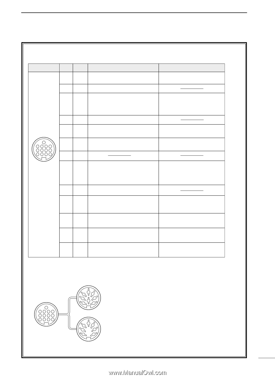
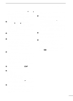
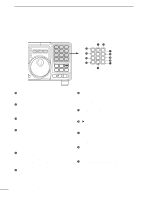
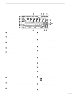
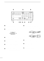
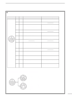
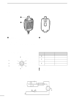
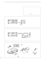
2 PANEL DESCRIPTION D ACC SOCKET INFORMATION • ACC socket ACC PIN # NAME DESCRIPTION 1 8V Regulated 8 V output. 2 GND Connects to ground. Input/output pin. 3 SEND Goes to ground when transmitting. When grounded, transmits. 13 9 10 11 12 5678 1234 Rear panel view 4 BDT Data line for the optional AT-180. 5 BAND Band voltage output. (Varies with amateur band) 6 ALC ALC voltage input. 7 NC 8 13.8 V 13.8 V output when power is ON. SPECIFICATIONS COLOR Output voltage Output current : 8 V ±0.3 V : Less than 10 mA brown red Ground level Input current : -0.5 V to 0.8 V : Less than 20 mA orange yellow Output voltage : 0 to 8.0 V green Control voltage : -4 to 0 V Input impedance : More than 10 kΩ blue purple Output current : Max. 1 A gray 9 TKEY Key line for the AT-180. 10 FSKK RTTY keying input. 11 MOD Modulator input. 12 AF AF detector output. Fixed, regardless of [AF] position. 13 SQLS Squelch output. Goes to ground when squelch opens. white Ground level Input current : -0.5 to 0.8 V : Less than 10 mA black Input impedance : 10 kΩ Input level : Approx. 100 mV pink rms Output impedance : 4.7 kΩ light Output level : 100 to 300 mV rms blue SQL open : Less than 0.3 V/5 mA light SQL closed : More than 6.0 V/100 µA green • When connecting the ACC conversion cable (OPC-599) 13 9 10 11 12 5678 1234 2 4 5 1 3 8 6 7 ACC 1 2 4 5 1 3 6 7 ACC 2 ➀ FSKK ➁ GND ➂ SEND ➃ MOD ➄ AF ➅ SQLS ➆ 13.8 V ➇ ALC ➀ 8 V ➁ GND ➂ SEND ➃ BAND ➄ ALC ➅ NC ➆ 13.8 V 7
-
 1
1 -
2
-
3
-
 4
4 -
 5
5 -
 6
6 -
 7
7 -
 8
8 -
 9
9 -
 10
10 -
 11
11 -
 12
12 -
 13
13 -
 14
14 -
15
-
16
-
17
-
18
-
19
-
20
-
21
-
22
-
23
-
24
-
25
-
26
-
27
-
28
-
29
-
30
-
31
-
32
-
33
-
34
-
35
-
36
-
37
-
38
-
39
-
40
-
41
-
42
-
43
-
44
-
45
-
46
-
47
-
48
-
49
-
50
-
51
-
52
-
53
-
54
-
55
-
56
-
57
-
58
-
59
-
60
-
61
-
62
 |
 |