Intel SC5400RA User Guide - Page 89
Removing Memory Riser Cards
 |
UPC - 675900759336
View all Intel SC5400RA manuals
Add to My Manuals
Save this manual to your list of manuals |
Page 89 highlights
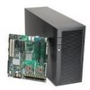
6. Pull the memory board(s) from the DIMM cage. See the following figure. Figure 70. Removing Memory Riser Cards AF001523 7. Push the clips at each end of the DIMM socket(s) outward to the open position. The FBDIMM lifts from the socket. 8. Holding the FBDIMM by the edges, lift it from the socket. Store the FBDIMM in an anti-static package. Note: For your server system to be functional, DIMMs must be installed in sockets DIMM_A1 and DIMM_B1 on memory riser card 1, and in sockets DIMM_C1 and DIMM_D1 on memory riser card 2. 9. Insert the memory board into the memory cage. Push down firmly to seat the memory board into the socket on the server board. 10. Close the door on the memory cage and tighten the thumbscrew on the cage. 11. Replace the chassis cover. For instructions, see "Installing the Chassis Cover" on page 25 12. Reconnect the AC power cord. Intel® Server System SC5400RA User's Guide 67
-
 1
1 -
2
-
3
-
4
-
5
-
6
-
7
-
8
-
9
-
10
-
11
-
12
-
13
-
14
-
15
-
16
-
17
-
18
-
19
-
20
-
21
-
22
-
23
-
24
-
25
-
26
-
27
-
28
-
29
-
30
-
31
-
32
-
33
-
34
-
35
-
36
-
37
-
38
-
39
-
40
-
41
-
42
-
43
-
44
-
45
-
46
-
47
-
48
-
49
-
50
-
51
-
52
-
53
-
54
-
55
-
56
-
57
-
58
-
59
-
60
-
61
-
62
-
63
-
64
-
65
-
66
-
67
-
68
-
69
-
70
-
71
-
72
-
73
-
74
-
75
-
76
-
77
-
78
-
79
-
80
-
81
-
82
-
83
-
 84
84 -
 85
85 -
 86
86 -
 87
87 -
 88
88 -
 89
89 -
 90
90 -
 91
91 -
 92
92 -
 93
93 -
 94
94 -
95
-
96
-
97
-
98
-
99
-
100
-
101
-
102
-
103
-
104
-
105
-
106
-
107
-
108
-
109
-
110
-
111
-
112
-
113
-
114
-
115
-
116
-
117
-
118
-
119
-
120
-
121
-
122
-
123
-
124
-
125
-
126
-
127
-
128
-
129
-
130
-
131
-
132
-
133
-
134
-
135
-
136
-
137
-
138
-
139
-
140
-
141
-
142
-
143
-
144
-
145
-
146
-
147
-
148
-
149
-
150
-
151
-
152
-
153
-
154
-
155
-
156
-
157
-
158
-
159
-
160
-
161
-
162
-
163
-
164
-
165
-
166
-
167
-
168
-
169
-
170
-
171
-
172
-
173
-
174
-
175
-
176
-
177
-
178
-
179
-
180
-
181
-
182
-
183
-
184
-
185
-
186
-
187
-
188
-
189
-
190
-
191
-
192
-
193
-
194
-
195
-
196
-
197
-
198
 |
 |
