Konica Minolta bizhub 160 Service Manual - Page 74
The Protective Metal Bracket is, tightened together with the Upper, Right Cover.
 |
View all Konica Minolta bizhub 160 manuals
Add to My Manuals
Save this manual to your list of manuals |
Page 74 highlights
bizhub 160/160f bizhub 161/161f Maintenance Field Service Ver. 1.0 Apr. 2005 6. Other 18. Remove the two screws. 19. Unhook the tab, and then remove the Left Rear Frame. 4980D010AC 4980E001AC 20. Remove the Upper Left Cover. 21. Remove the two screws. 22. Remove the Upper Right Cover and Protective Metal Bracket. NOTE • The Protective Metal Bracket is tightened together with the Upper Right Cover. 23. Remove the two screws. 24. Unplug the three connectors. 25. Remove the Fusing Unit Assy. 4980E002AA 26. Remove three screws. 27. Remove the Power Switch stay. 28. Remove the Power Switch. 4980D011AC 29. Remove four screws. 30. Disconnect three connectors. 31. Remove the Power Unit Assy. 4980f2c001aa 41
-
 1
1 -
2
-
3
-
4
-
5
-
6
-
7
-
8
-
9
-
10
-
11
-
12
-
13
-
14
-
15
-
16
-
17
-
18
-
19
-
20
-
21
-
22
-
23
-
24
-
25
-
26
-
27
-
28
-
29
-
30
-
31
-
32
-
33
-
34
-
35
-
36
-
37
-
38
-
39
-
40
-
41
-
42
-
43
-
44
-
45
-
46
-
47
-
48
-
49
-
50
-
51
-
52
-
53
-
54
-
55
-
56
-
57
-
58
-
59
-
60
-
61
-
62
-
63
-
64
-
65
-
66
-
67
-
68
-
 69
69 -
 70
70 -
 71
71 -
 72
72 -
 73
73 -
 74
74 -
 75
75 -
 76
76 -
 77
77 -
 78
78 -
 79
79 -
80
-
81
-
82
-
83
-
84
-
85
-
86
-
87
-
88
-
89
-
90
-
91
-
92
-
93
-
94
-
95
-
96
-
97
-
98
-
99
-
100
-
101
-
102
-
103
-
104
-
105
-
106
-
107
-
108
-
109
-
110
-
111
-
112
-
113
-
114
-
115
-
116
-
117
-
118
-
119
-
120
-
121
-
122
-
123
-
124
-
125
-
126
-
127
-
128
-
129
-
130
-
131
-
132
-
133
-
134
-
135
-
136
-
137
-
138
-
139
-
140
-
141
-
142
-
143
-
144
-
145
-
146
-
147
-
148
-
149
-
150
-
151
-
152
-
153
-
154
-
155
-
156
-
157
-
158
-
159
-
160
-
161
-
162
-
163
-
164
-
165
-
166
-
167
-
168
-
169
-
170
-
171
-
172
-
173
-
174
-
175
-
176
-
177
-
178
-
179
-
180
-
181
-
182
-
183
-
184
-
185
-
186
-
187
-
188
-
189
-
190
-
191
-
192
-
193
-
194
-
195
-
196
-
197
-
198
-
199
-
200
-
201
-
202
-
203
-
204
-
205
-
206
-
207
-
208
-
209
-
210
-
211
-
212
-
213
-
214
-
215
-
216
-
217
-
218
-
219
-
220
-
221
-
222
-
223
-
224
-
225
-
226
-
227
-
228
-
229
-
230
-
231
-
232
-
233
-
234
-
235
-
236
-
237
-
238
-
239
-
240
-
241
-
242
-
243
-
244
-
245
-
246
-
247
-
248
-
249
-
250
-
251
-
252
-
253
-
254
-
255
-
256
-
257
-
258
-
259
-
260
-
261
-
262
-
263
-
264
-
265
-
266
-
267
-
268
-
269
-
270
-
271
-
272
-
273
-
274
-
275
-
276
-
277
-
278
-
279
-
280
-
281
-
282
-
283
-
284
-
285
-
286
-
287
-
288
-
289
-
290
-
291
-
292
-
293
-
294
-
295
-
296
-
297
-
298
-
299
-
300
-
301
-
302
-
303
-
304
-
305
-
306
-
307
-
308
-
309
-
310
-
311
-
312
-
313
-
314
-
315
-
316
-
317
-
318
-
319
-
320
-
321
-
322
-
323
-
324
-
325
-
326
-
327
-
328
-
329
-
330
-
331
-
332
-
333
-
334
-
335
-
336
-
337
-
338
-
339
-
340
-
341
-
342
-
343
-
344
-
345
-
346
-
347
-
348
-
349
-
350
-
351
-
352
-
353
-
354
-
355
-
356
-
357
-
358
-
359
-
360
-
361
-
362
-
363
-
364
-
365
-
366
-
367
-
368
-
369
-
370
-
371
-
372
-
373
-
374
-
375
-
376
 |
 |

Field Service Ver. 1.0 Apr. 2005
6. Other
41
bizhub 160/160f
bizhub 161/161f
Maintenance
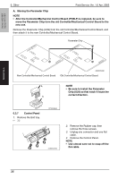
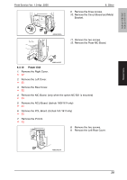
18.
Remove the two screws.
19.
Unhook the tab, and then remove the
Left Rear Frame.
20.
Remove the Upper Left Cover.
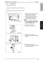
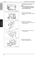
21.
Remove the two screws.
22.
Remove the Upper Right Cover and
Protective Metal Bracket.
NOTE
•
The Protective Metal Bracket is
tightened together with the Upper
Right Cover.
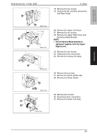
23.
Remove the two screws.
24.
Unplug the three connectors.
25.
Remove the Fusing Unit Assy.
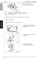
26.
Remove three screws.
27.
Remove the Power Switch stay.
28.
Remove the Power Switch.
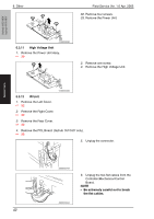
29.
Remove four screws.
30.
Disconnect three connectors.
31.
Remove the Power Unit Assy.
4980D010AC
4980E001AC
4980E002AA
4980D011AC
4980f2c001aa