Lenovo ThinkCentre A70 Hardware Maintenance Manual for ThinkCentre A70 - Page 117
then completely remove screw, Loosen screw
 |
View all Lenovo ThinkCentre A70 manuals
Add to My Manuals
Save this manual to your list of manuals |
Page 117 highlights
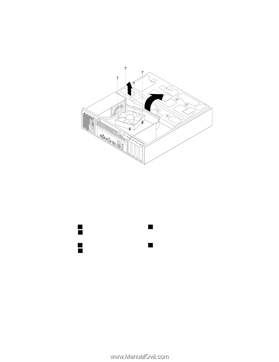
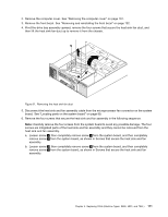
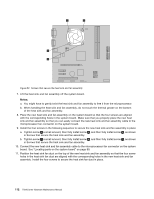
2. Remove the computer cover. See "Removing the computer cover" on page 101. 3. Remove the front bezel. See "Removing and reinstalling the front bezel" on page 102. 4. Pivot the drive bay assembly upward, remove the four screws that secure the heat sink fan duct, and then lift the heat sink fan duct up to remove it from the chassis. Figure 51. Removing the heat sink fan duct 5. Disconnect the heat sink and fan assembly cable from the microprocessor fan connector on the system board. See "Locating parts on the system board" on page 99. 6. Remove the four screws that secure the heat sink and fan assembly in the following sequence: Note: Carefully remove the four screws from the system board to avoid any possible damage. The four screws are integrated parts of the heat sink and fan assembly and they cannot be removed from the heat sink and fan assembly. a. Loosen screw 1 , then completely remove screw 3 from the system board, and then completely remove screw 1 from the system board, as shown in Screws that secure the heat sink and fan assembly. b. Loosen screw 2 , then completely remove screw 4 from the system board, and then completely remove screw 2 from the system board, as shown in Screws that secure the heat sink and fan assembly. Chapter 9. Replacing FRUs (Machine Types: 0889, 5023, and 7844.) 111
-
 1
1 -
2
-
3
-
4
-
5
-
6
-
7
-
8
-
9
-
10
-
11
-
12
-
13
-
14
-
15
-
16
-
17
-
18
-
19
-
20
-
21
-
22
-
23
-
24
-
25
-
26
-
27
-
28
-
29
-
30
-
31
-
32
-
33
-
34
-
35
-
36
-
37
-
38
-
39
-
40
-
41
-
42
-
43
-
44
-
45
-
46
-
47
-
48
-
49
-
50
-
51
-
52
-
53
-
54
-
55
-
56
-
57
-
58
-
59
-
60
-
61
-
62
-
63
-
64
-
65
-
66
-
67
-
68
-
69
-
70
-
71
-
72
-
73
-
74
-
75
-
76
-
77
-
78
-
79
-
80
-
81
-
82
-
83
-
84
-
85
-
86
-
87
-
88
-
89
-
90
-
91
-
92
-
93
-
94
-
95
-
96
-
97
-
98
-
99
-
100
-
101
-
102
-
103
-
104
-
105
-
106
-
107
-
108
-
109
-
110
-
111
-
 112
112 -
 113
113 -
 114
114 -
 115
115 -
 116
116 -
 117
117 -
 118
118 -
 119
119 -
 120
120 -
 121
121 -
 122
122 -
123
-
124
-
125
-
126
-
127
-
128
-
129
-
130
-
131
-
132
-
133
-
134
-
135
-
136
-
137
-
138
-
139
-
140
-
141
-
142
-
143
-
144
-
145
-
146
-
147
-
148
-
149
-
150
-
151
-
152
-
153
-
154
-
155
-
156
-
157
-
158
-
159
-
160
-
161
-
162
-
163
-
164
-
165
-
166
-
167
-
168
-
169
-
170
-
171
-
172
-
173
-
174
-
175
-
176
-
177
-
178
-
179
-
180
-
181
-
182
-
183
-
184
-
185
-
186
-
187
-
188
-
189
-
190
-
191
-
192
-
193
-
194
-
195
-
196
-
197
-
198
-
199
-
200
-
201
-
202
-
203
-
204
-
205
-
206
-
207
-
208
-
209
-
210
-
211
-
212
-
213
-
214
-
215
-
216
-
217
-
218
-
219
-
220
-
221
-
222
-
223
-
224
-
225
-
226
-
227
-
228
-
229
-
230
-
231
-
232
-
233
-
234
-
235
-
236
-
237
-
238
-
239
-
240
-
241
-
242
-
243
-
244
-
245
-
246
-
247
-
248
-
249
-
250
-
251
-
252
-
253
-
254
-
255
-
256
-
257
-
258
-
259
-
260
-
261
-
262
-
263
-
264
-
265
-
266
-
267
-
268
-
269
-
270
 |
 |