Lenovo ThinkCentre A70 Hardware Maintenance Manual for ThinkCentre A70 - Page 139
and is closed. Then, install the two screws to secure the computer cover., engage the rails. Then
 |
View all Lenovo ThinkCentre A70 manuals
Add to My Manuals
Save this manual to your list of manuals |
Page 139 highlights
Figure 76. Cable routing (For a clear illustration of the cable routing, some components are not shown here.) 3. Lower the drive bay assembly. See "Accessing the system board components and drives" on page 104. 4. Reinstall the front bezel. See "Removing and reinstalling the front bezel" on page 102. 5. Position the computer cover on the chassis so that the rail guides on the bottom of the computer cover engage the rails. Then, slide the computer cover to the front of the computer until it snaps into position and is closed. Then, install the two screws to secure the computer cover. Figure 77. Reinstalling the computer cover Chapter 9. Replacing FRUs (Machine Types: 0889, 5023, and 7844.) 133
-
 1
1 -
2
-
3
-
4
-
5
-
6
-
7
-
8
-
9
-
10
-
11
-
12
-
13
-
14
-
15
-
16
-
17
-
18
-
19
-
20
-
21
-
22
-
23
-
24
-
25
-
26
-
27
-
28
-
29
-
30
-
31
-
32
-
33
-
34
-
35
-
36
-
37
-
38
-
39
-
40
-
41
-
42
-
43
-
44
-
45
-
46
-
47
-
48
-
49
-
50
-
51
-
52
-
53
-
54
-
55
-
56
-
57
-
58
-
59
-
60
-
61
-
62
-
63
-
64
-
65
-
66
-
67
-
68
-
69
-
70
-
71
-
72
-
73
-
74
-
75
-
76
-
77
-
78
-
79
-
80
-
81
-
82
-
83
-
84
-
85
-
86
-
87
-
88
-
89
-
90
-
91
-
92
-
93
-
94
-
95
-
96
-
97
-
98
-
99
-
100
-
101
-
102
-
103
-
104
-
105
-
106
-
107
-
108
-
109
-
110
-
111
-
112
-
113
-
114
-
115
-
116
-
117
-
118
-
119
-
120
-
121
-
122
-
123
-
124
-
125
-
126
-
127
-
128
-
129
-
130
-
131
-
132
-
133
-
 134
134 -
 135
135 -
 136
136 -
 137
137 -
 138
138 -
 139
139 -
 140
140 -
 141
141 -
 142
142 -
 143
143 -
 144
144 -
145
-
146
-
147
-
148
-
149
-
150
-
151
-
152
-
153
-
154
-
155
-
156
-
157
-
158
-
159
-
160
-
161
-
162
-
163
-
164
-
165
-
166
-
167
-
168
-
169
-
170
-
171
-
172
-
173
-
174
-
175
-
176
-
177
-
178
-
179
-
180
-
181
-
182
-
183
-
184
-
185
-
186
-
187
-
188
-
189
-
190
-
191
-
192
-
193
-
194
-
195
-
196
-
197
-
198
-
199
-
200
-
201
-
202
-
203
-
204
-
205
-
206
-
207
-
208
-
209
-
210
-
211
-
212
-
213
-
214
-
215
-
216
-
217
-
218
-
219
-
220
-
221
-
222
-
223
-
224
-
225
-
226
-
227
-
228
-
229
-
230
-
231
-
232
-
233
-
234
-
235
-
236
-
237
-
238
-
239
-
240
-
241
-
242
-
243
-
244
-
245
-
246
-
247
-
248
-
249
-
250
-
251
-
252
-
253
-
254
-
255
-
256
-
257
-
258
-
259
-
260
-
261
-
262
-
263
-
264
-
265
-
266
-
267
-
268
-
269
-
270
 |
 |
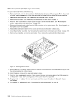
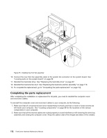
Figure 76. Cable routing (For a clear illustration of the cable routing, some components are not shown here.)
3. Lower the drive bay assembly. See “Accessing the system board components and drives” on page 104.
4. Reinstall the front bezel. See “Removing and reinstalling the front bezel” on page 102.
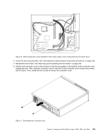
5. Position the computer cover on the chassis so that the rail guides on the bottom of the computer cover
engage the rails. Then, slide the computer cover to the front of the computer until it snaps into position
and is closed. Then, install the two screws to secure the computer cover.
Figure 77. Reinstalling the computer cover
Chapter 9
.
Replacing FRUs (Machine Types: 0889, 5023, and 7844.)
133