Lenovo ThinkCentre A70 Hardware Maintenance Manual for ThinkCentre A70 - Page 129
Replacing the system board, the system board
 |
View all Lenovo ThinkCentre A70 manuals
Add to My Manuals
Save this manual to your list of manuals |
Page 129 highlights
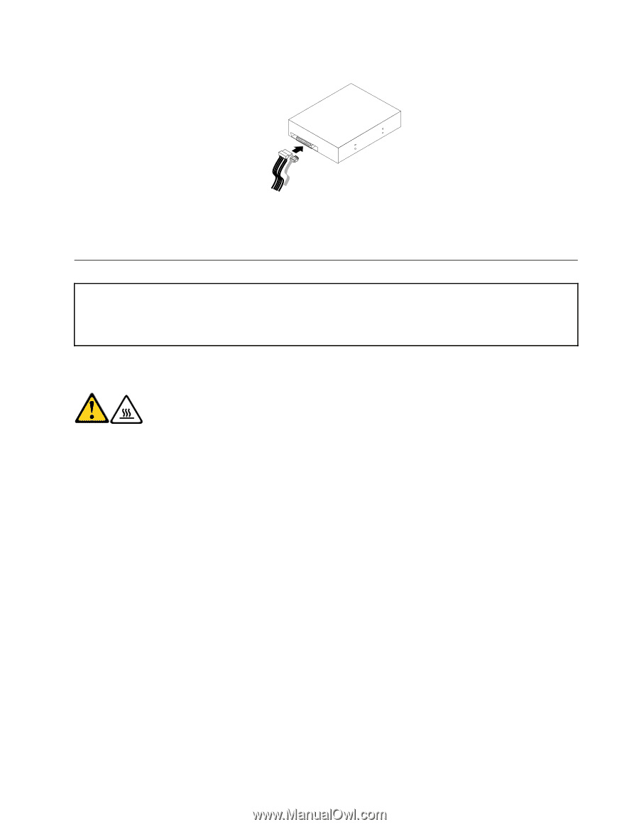
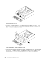
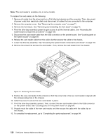
Figure 64. Connecting a SATA optical drive 12. To complete the replacement, go to "Completing the parts replacement" on page 132. Replacing the system board Attention Do not open your computer or attempt any repair before reading and understanding the "Important safety information" in the ThinkCentre Safety and Warranty Guide that came with your computer. To obtain a copy of the ThinkCentre Safety and Warranty Guide, go to:http://www.lenovo.com/support This section provides instructions on how to replace the system board. CAUTION: The heat sink and microprocessor might be very hot. Turn off the computer and wait three to five minutes to let the computer cool before opening the computer cover. To replace the system board: 1. Remove all media from the drives and turn off all attached devices and the computer. Then, disconnect all power cords from electrical outlets and disconnect all cables that are connected to the computer. 2. Remove the computer cover. See "Removing the computer cover" on page 101. 3. Remove the front bezel. See "Removing and reinstalling the front bezel" on page 102. 4. Lay the computer on its side for easier access to the system board. Pivot the drive bay assembly upward to gain access to the system board. See "Accessing the system board components and drives" on page 104. 5. Disconnect the front audio and USB assembly cables from the system board. See "Locating parts on the system board" on page 99. 6. Remove all memory modules and PCI cards that are currently installed. See "Installing or replacing a memory module" on page 107 and "Installing or replacing a PCI card" on page 105. 7. Remove the heat sink and fan assembly from the failing system board. See "Replacing the heat sink and fan assembly" on page 110. 8. Carefully take note of the location of all cable connections on the system board and disconnect all the cables. See "Locating parts on the system board" on page 99. 9. Remove the six screws that secure the system board. Chapter 9. Replacing FRUs (Machine Types: 0889, 5023, and 7844.) 123
-
 1
1 -
2
-
3
-
4
-
5
-
6
-
7
-
8
-
9
-
10
-
11
-
12
-
13
-
14
-
15
-
16
-
17
-
18
-
19
-
20
-
21
-
22
-
23
-
24
-
25
-
26
-
27
-
28
-
29
-
30
-
31
-
32
-
33
-
34
-
35
-
36
-
37
-
38
-
39
-
40
-
41
-
42
-
43
-
44
-
45
-
46
-
47
-
48
-
49
-
50
-
51
-
52
-
53
-
54
-
55
-
56
-
57
-
58
-
59
-
60
-
61
-
62
-
63
-
64
-
65
-
66
-
67
-
68
-
69
-
70
-
71
-
72
-
73
-
74
-
75
-
76
-
77
-
78
-
79
-
80
-
81
-
82
-
83
-
84
-
85
-
86
-
87
-
88
-
89
-
90
-
91
-
92
-
93
-
94
-
95
-
96
-
97
-
98
-
99
-
100
-
101
-
102
-
103
-
104
-
105
-
106
-
107
-
108
-
109
-
110
-
111
-
112
-
113
-
114
-
115
-
116
-
117
-
118
-
119
-
120
-
121
-
122
-
123
-
 124
124 -
 125
125 -
 126
126 -
 127
127 -
 128
128 -
 129
129 -
 130
130 -
 131
131 -
 132
132 -
 133
133 -
 134
134 -
135
-
136
-
137
-
138
-
139
-
140
-
141
-
142
-
143
-
144
-
145
-
146
-
147
-
148
-
149
-
150
-
151
-
152
-
153
-
154
-
155
-
156
-
157
-
158
-
159
-
160
-
161
-
162
-
163
-
164
-
165
-
166
-
167
-
168
-
169
-
170
-
171
-
172
-
173
-
174
-
175
-
176
-
177
-
178
-
179
-
180
-
181
-
182
-
183
-
184
-
185
-
186
-
187
-
188
-
189
-
190
-
191
-
192
-
193
-
194
-
195
-
196
-
197
-
198
-
199
-
200
-
201
-
202
-
203
-
204
-
205
-
206
-
207
-
208
-
209
-
210
-
211
-
212
-
213
-
214
-
215
-
216
-
217
-
218
-
219
-
220
-
221
-
222
-
223
-
224
-
225
-
226
-
227
-
228
-
229
-
230
-
231
-
232
-
233
-
234
-
235
-
236
-
237
-
238
-
239
-
240
-
241
-
242
-
243
-
244
-
245
-
246
-
247
-
248
-
249
-
250
-
251
-
252
-
253
-
254
-
255
-
256
-
257
-
258
-
259
-
260
-
261
-
262
-
263
-
264
-
265
-
266
-
267
-
268
-
269
-
270
 |
 |