Lenovo ThinkCentre A70 Hardware Maintenance Manual for ThinkCentre A70 - Page 137
The new front fan assembly will have four new rubber mounts attached., holes. Then
 |
View all Lenovo ThinkCentre A70 manuals
Add to My Manuals
Save this manual to your list of manuals |
Page 137 highlights
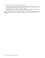
Figure 74. Removing the front fan assembly 9. Install the new front fan assembly by aligning the new rubber mounts that came with the new front fan assembly with the corresponding holes in the chassis, and then push the rubber mounts through the holes. Then, carefully pull on the tips of the rubber mounts from the bottom side until the new front fan assembly is secured in place. Note: The new front fan assembly will have four new rubber mounts attached. Chapter 9. Replacing FRUs (Machine Types: 0889, 5023, and 7844.) 131
-
 1
1 -
2
-
3
-
4
-
5
-
6
-
7
-
8
-
9
-
10
-
11
-
12
-
13
-
14
-
15
-
16
-
17
-
18
-
19
-
20
-
21
-
22
-
23
-
24
-
25
-
26
-
27
-
28
-
29
-
30
-
31
-
32
-
33
-
34
-
35
-
36
-
37
-
38
-
39
-
40
-
41
-
42
-
43
-
44
-
45
-
46
-
47
-
48
-
49
-
50
-
51
-
52
-
53
-
54
-
55
-
56
-
57
-
58
-
59
-
60
-
61
-
62
-
63
-
64
-
65
-
66
-
67
-
68
-
69
-
70
-
71
-
72
-
73
-
74
-
75
-
76
-
77
-
78
-
79
-
80
-
81
-
82
-
83
-
84
-
85
-
86
-
87
-
88
-
89
-
90
-
91
-
92
-
93
-
94
-
95
-
96
-
97
-
98
-
99
-
100
-
101
-
102
-
103
-
104
-
105
-
106
-
107
-
108
-
109
-
110
-
111
-
112
-
113
-
114
-
115
-
116
-
117
-
118
-
119
-
120
-
121
-
122
-
123
-
124
-
125
-
126
-
127
-
128
-
129
-
130
-
131
-
 132
132 -
 133
133 -
 134
134 -
 135
135 -
 136
136 -
 137
137 -
 138
138 -
 139
139 -
 140
140 -
 141
141 -
 142
142 -
143
-
144
-
145
-
146
-
147
-
148
-
149
-
150
-
151
-
152
-
153
-
154
-
155
-
156
-
157
-
158
-
159
-
160
-
161
-
162
-
163
-
164
-
165
-
166
-
167
-
168
-
169
-
170
-
171
-
172
-
173
-
174
-
175
-
176
-
177
-
178
-
179
-
180
-
181
-
182
-
183
-
184
-
185
-
186
-
187
-
188
-
189
-
190
-
191
-
192
-
193
-
194
-
195
-
196
-
197
-
198
-
199
-
200
-
201
-
202
-
203
-
204
-
205
-
206
-
207
-
208
-
209
-
210
-
211
-
212
-
213
-
214
-
215
-
216
-
217
-
218
-
219
-
220
-
221
-
222
-
223
-
224
-
225
-
226
-
227
-
228
-
229
-
230
-
231
-
232
-
233
-
234
-
235
-
236
-
237
-
238
-
239
-
240
-
241
-
242
-
243
-
244
-
245
-
246
-
247
-
248
-
249
-
250
-
251
-
252
-
253
-
254
-
255
-
256
-
257
-
258
-
259
-
260
-
261
-
262
-
263
-
264
-
265
-
266
-
267
-
268
-
269
-
270
 |
 |
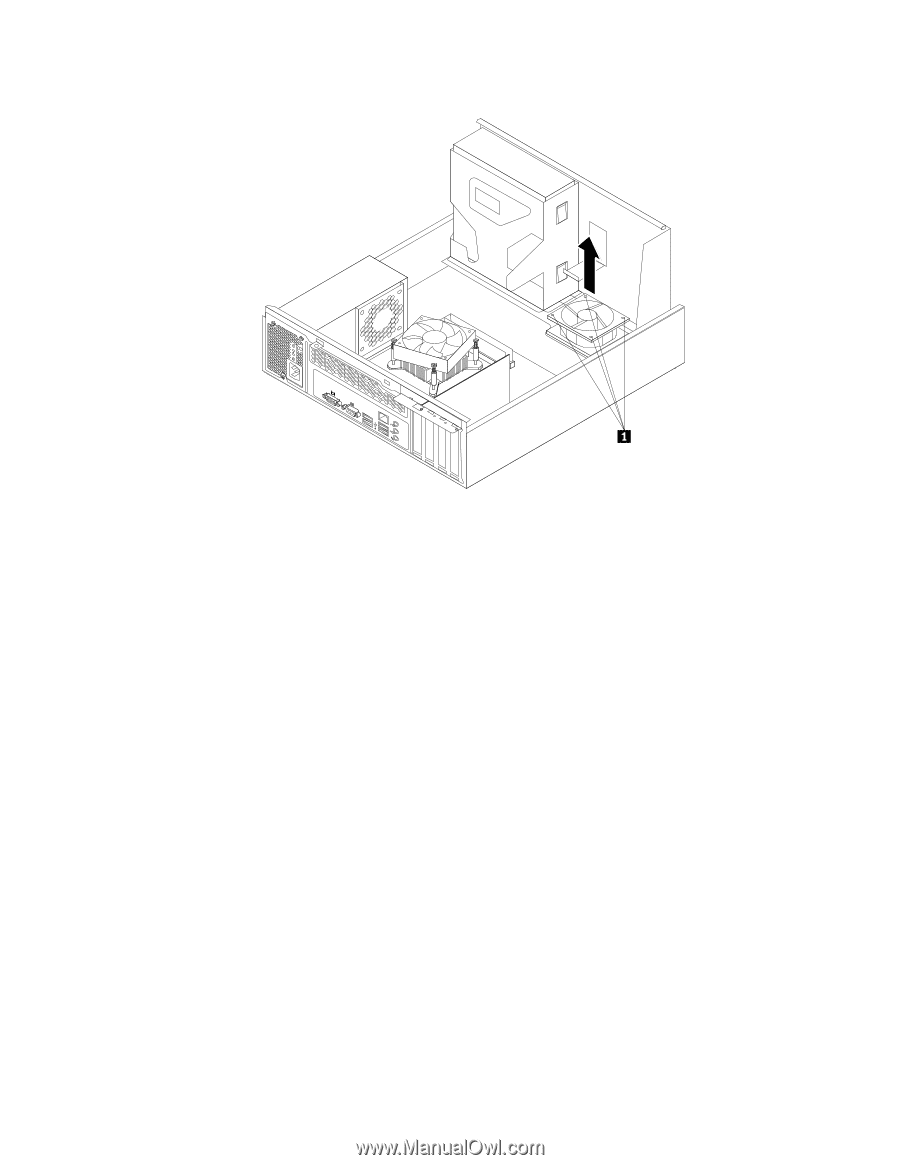
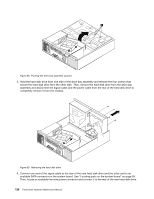
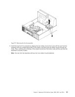
Figure 74. Removing the front fan assembly
9. Install the new front fan assembly by aligning the new rubber mounts that came with the new front fan
assembly with the corresponding holes in the chassis, and then push the rubber mounts through the
holes. Then, carefully pull on the tips of the rubber mounts from the bottom side until the new front fan
assembly is secured in place.
Note:
The new front fan assembly will have four new rubber mounts attached.
Chapter 9
.
Replacing FRUs (Machine Types: 0889, 5023, and 7844.)
131