Lenovo ThinkCentre A70 Hardware Maintenance Manual for ThinkCentre A70 - Page 128
SATA connector on the system board. See Locating parts on the system board on Then
 |
View all Lenovo ThinkCentre A70 manuals
Add to My Manuals
Save this manual to your list of manuals |
Page 128 highlights
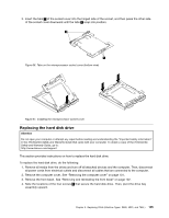
Figure 62. Installing the optical drive 10. Hold the new optical drive and pivot the drive bay assembly upward. Align the screw holes in the new optical drive with the corresponding holes in the side of the drive bay assembly. Then, install the two screws to secure the new optical drive in place. Figure 63. Installing the two screws to secure the optical drive 11. Connect one end of the signal cable to the rear of the new optical drive and the other end to an available SATA connector on the system board. See "Locating parts on the system board" on page 99. Then, locate an available five-wire power connector and connect it to the rear of the new optical drive. 122 ThinkCentre Hardware Maintenance Manual
-
 1
1 -
2
-
3
-
4
-
5
-
6
-
7
-
8
-
9
-
10
-
11
-
12
-
13
-
14
-
15
-
16
-
17
-
18
-
19
-
20
-
21
-
22
-
23
-
24
-
25
-
26
-
27
-
28
-
29
-
30
-
31
-
32
-
33
-
34
-
35
-
36
-
37
-
38
-
39
-
40
-
41
-
42
-
43
-
44
-
45
-
46
-
47
-
48
-
49
-
50
-
51
-
52
-
53
-
54
-
55
-
56
-
57
-
58
-
59
-
60
-
61
-
62
-
63
-
64
-
65
-
66
-
67
-
68
-
69
-
70
-
71
-
72
-
73
-
74
-
75
-
76
-
77
-
78
-
79
-
80
-
81
-
82
-
83
-
84
-
85
-
86
-
87
-
88
-
89
-
90
-
91
-
92
-
93
-
94
-
95
-
96
-
97
-
98
-
99
-
100
-
101
-
102
-
103
-
104
-
105
-
106
-
107
-
108
-
109
-
110
-
111
-
112
-
113
-
114
-
115
-
116
-
117
-
118
-
119
-
120
-
121
-
122
-
 123
123 -
 124
124 -
 125
125 -
 126
126 -
 127
127 -
 128
128 -
 129
129 -
 130
130 -
 131
131 -
 132
132 -
 133
133 -
134
-
135
-
136
-
137
-
138
-
139
-
140
-
141
-
142
-
143
-
144
-
145
-
146
-
147
-
148
-
149
-
150
-
151
-
152
-
153
-
154
-
155
-
156
-
157
-
158
-
159
-
160
-
161
-
162
-
163
-
164
-
165
-
166
-
167
-
168
-
169
-
170
-
171
-
172
-
173
-
174
-
175
-
176
-
177
-
178
-
179
-
180
-
181
-
182
-
183
-
184
-
185
-
186
-
187
-
188
-
189
-
190
-
191
-
192
-
193
-
194
-
195
-
196
-
197
-
198
-
199
-
200
-
201
-
202
-
203
-
204
-
205
-
206
-
207
-
208
-
209
-
210
-
211
-
212
-
213
-
214
-
215
-
216
-
217
-
218
-
219
-
220
-
221
-
222
-
223
-
224
-
225
-
226
-
227
-
228
-
229
-
230
-
231
-
232
-
233
-
234
-
235
-
236
-
237
-
238
-
239
-
240
-
241
-
242
-
243
-
244
-
245
-
246
-
247
-
248
-
249
-
250
-
251
-
252
-
253
-
254
-
255
-
256
-
257
-
258
-
259
-
260
-
261
-
262
-
263
-
264
-
265
-
266
-
267
-
268
-
269
-
270
 |
 |
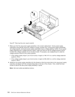
Figure 62. Installing the optical drive
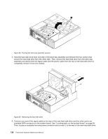
10. Hold the new optical drive and pivot the drive bay assembly upward. Align the screw holes in the new
optical drive with the corresponding holes in the side of the drive bay assembly. Then, install the two
screws to secure the new optical drive in place.
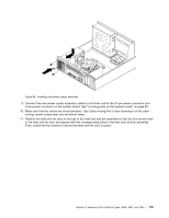
Figure 63. Installing the two screws to secure the optical drive
11. Connect one end of the signal cable to the rear of the new optical drive and the other end to an available
SATA connector on the system board. See “Locating parts on the system board” on page 99. Then,
locate an available five-wire power connector and connect it to the rear of the new optical drive.
122
ThinkCentre Hardware Maintenance Manual