Lenovo ThinkCentre M76 Hardware Maintenance Manual for ThinkCentre M76 - Page 115
Position the computer cover on the chassis so that the rail guides on the bottom of the computer
 |
View all Lenovo ThinkCentre M76 manuals
Add to My Manuals
Save this manual to your list of manuals |
Page 115 highlights
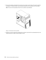
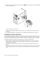
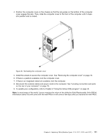
4. Position the computer cover on the chassis so that the rail guides on the bottom of the computer cover engage the rails. Then, slide the computer cover to the front of the computer until it snaps into position and is closed. Figure 46. Reinstalling the computer cover 5. Install the screws to secure the computer cover. See "Removing the computer cover" on page 78. 6. If there is a padlock available, lock the computer cover. 7. If there is an integrated cable lock available, lock the computer. 8. Reconnect the external cables and power cords to the computer. See "Locating connectors and parts on the rear of your computer" on page 73. 9. To update your configuration, refer to Chapter 6 "Using the Setup Utility program" on page 43. Note: In most areas of the world, Lenovo requires the return of the defective Field Replaceable Units (FRUs). Information about this will come with the new FRUs or will come a few days after you receive the new FRUs. Chapter 8. Replacing FRUs (Machine Types: 3114, 3121, 3123, and 3127.) 111
-
 1
1 -
2
-
3
-
4
-
5
-
6
-
7
-
8
-
9
-
10
-
11
-
12
-
13
-
14
-
15
-
16
-
17
-
18
-
19
-
20
-
21
-
22
-
23
-
24
-
25
-
26
-
27
-
28
-
29
-
30
-
31
-
32
-
33
-
34
-
35
-
36
-
37
-
38
-
39
-
40
-
41
-
42
-
43
-
44
-
45
-
46
-
47
-
48
-
49
-
50
-
51
-
52
-
53
-
54
-
55
-
56
-
57
-
58
-
59
-
60
-
61
-
62
-
63
-
64
-
65
-
66
-
67
-
68
-
69
-
70
-
71
-
72
-
73
-
74
-
75
-
76
-
77
-
78
-
79
-
80
-
81
-
82
-
83
-
84
-
85
-
86
-
87
-
88
-
89
-
90
-
91
-
92
-
93
-
94
-
95
-
96
-
97
-
98
-
99
-
100
-
101
-
102
-
103
-
104
-
105
-
106
-
107
-
108
-
109
-
 110
110 -
 111
111 -
 112
112 -
 113
113 -
 114
114 -
 115
115 -
 116
116 -
 117
117 -
 118
118 -
 119
119 -
 120
120 -
121
-
122
-
123
-
124
-
125
-
126
-
127
-
128
-
129
-
130
-
131
-
132
-
133
-
134
-
135
-
136
-
137
-
138
-
139
-
140
-
141
-
142
-
143
-
144
-
145
-
146
-
147
-
148
-
149
-
150
-
151
-
152
-
153
-
154
-
155
-
156
-
157
-
158
-
159
-
160
-
161
-
162
-
163
-
164
-
165
-
166
-
167
-
168
-
169
-
170
-
171
-
172
-
173
-
174
-
175
-
176
-
177
-
178
-
179
-
180
-
181
-
182
-
183
-
184
-
185
-
186
-
187
-
188
-
189
-
190
-
191
-
192
-
193
-
194
-
195
-
196
-
197
-
198
-
199
-
200
-
201
-
202
-
203
-
204
-
205
-
206
-
207
-
208
-
209
-
210
-
211
-
212
-
213
-
214
 |
 |
