Lenovo ThinkCentre M76 Hardware Maintenance Manual for ThinkCentre M76 - Page 207
Power management, Advanced Configuration and Power Interface (ACPI) BIOS, Automatic Power-On features
 |
View all Lenovo ThinkCentre M76 manuals
Add to My Manuals
Save this manual to your list of manuals |
Page 207 highlights
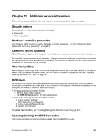
2. Remove or open the computer cover. For machine types 3114, 3121, 3123, and 3127, see "Removing the computer cover" on page 78. For machine types 3120, 3122, 3126, and 3128, see "Opening the computer cover" on page 119. 3. Locate the Clear CMOS /Recovery jumper on the system board. See "Locating parts on the system board" on page 76. 4. Remove any parts and disconnect any cables that might prevent your access to the Clear CMOS /Recovery jumper. 5. Move the jumper from the standard position (pin 1 and pin 2) to the maintenance position (pin 2 and pin 3). 6. Reinstall any parts and reconnect any cables that have been removed or disconnected. 7. Reinstall or close the computer cover and reconnect the power cords for the computer and monitor. For machine types 3114, 3121, 3123, and 3127, see "Completing the parts replacement" on page 110. For machine types 3120, 3122, 3126, and 3128, see "Completing the parts replacement" on page 157. 8. Turn on the computer and then insert the POST and BIOS update (flash update) disc into the optical drive. The recovery session begins. The recovery session will take two to three minutes. During this time, you will hear a series of beeps. 9. After the recovery session is completed, there will be no video, the series of beeps will end, and the system will automatically turn off. 10. Repeat step 1 through step 4. 11. Move the jumper back to the standard position (pin 1 and pin 2). 12. Reinstall any parts and reconnect any cables that have been removed or disconnected. 13. Reinstall or close the computer cover and reconnect power cords and all other external cables. For machine types 3114, 3121, 3123, and 3127, see "Completing the parts replacement" on page 110. For machine types 3120, 3122, 3126, and 3128, see "Completing the parts replacement" on page 157. 14. Turn on the computer and remove the disc from the optical drive. Power management Power management reduces the power consumption of certain components of the computer such as the system power supply, processor, hard disk drives, and some monitors. Advanced Configuration and Power Interface (ACPI) BIOS Being an ACPI BIOS system, the operating system is allowed to control the power management features of the computer and the setting for Advanced Power Management (APM) BIOS mode is ignored. Not all operating systems support ACPI BIOS mode. Automatic Power-On features The Automatic Power-On features within the Power Management menu allow you to enable and disable features that turn on the computer automatically. • RTC resume: You can specify a date and time at which the computer will be turned on automatically. This can be either a single event or a daily event. • Wake on LAN: If the computer has a properly configured token-ring or Ethernet LAN adapter card that is Wake on LAN-enabled and there is remote network management software, you can use the Wake on LAN feature. When you set Wake on LAN to Enabled, the computer will turn on when it receives a specific signal from another computer on the local area network (LAN). Chapter 11. Additional service information 203
-
 1
1 -
2
-
3
-
4
-
5
-
6
-
7
-
8
-
9
-
10
-
11
-
12
-
13
-
14
-
15
-
16
-
17
-
18
-
19
-
20
-
21
-
22
-
23
-
24
-
25
-
26
-
27
-
28
-
29
-
30
-
31
-
32
-
33
-
34
-
35
-
36
-
37
-
38
-
39
-
40
-
41
-
42
-
43
-
44
-
45
-
46
-
47
-
48
-
49
-
50
-
51
-
52
-
53
-
54
-
55
-
56
-
57
-
58
-
59
-
60
-
61
-
62
-
63
-
64
-
65
-
66
-
67
-
68
-
69
-
70
-
71
-
72
-
73
-
74
-
75
-
76
-
77
-
78
-
79
-
80
-
81
-
82
-
83
-
84
-
85
-
86
-
87
-
88
-
89
-
90
-
91
-
92
-
93
-
94
-
95
-
96
-
97
-
98
-
99
-
100
-
101
-
102
-
103
-
104
-
105
-
106
-
107
-
108
-
109
-
110
-
111
-
112
-
113
-
114
-
115
-
116
-
117
-
118
-
119
-
120
-
121
-
122
-
123
-
124
-
125
-
126
-
127
-
128
-
129
-
130
-
131
-
132
-
133
-
134
-
135
-
136
-
137
-
138
-
139
-
140
-
141
-
142
-
143
-
144
-
145
-
146
-
147
-
148
-
149
-
150
-
151
-
152
-
153
-
154
-
155
-
156
-
157
-
158
-
159
-
160
-
161
-
162
-
163
-
164
-
165
-
166
-
167
-
168
-
169
-
170
-
171
-
172
-
173
-
174
-
175
-
176
-
177
-
178
-
179
-
180
-
181
-
182
-
183
-
184
-
185
-
186
-
187
-
188
-
189
-
190
-
191
-
192
-
193
-
194
-
195
-
196
-
197
-
198
-
199
-
200
-
201
-
 202
202 -
 203
203 -
 204
204 -
 205
205 -
 206
206 -
 207
207 -
 208
208 -
 209
209 -
 210
210 -
 211
211 -
 212
212 -
213
-
214
 |
 |