Lenovo ThinkCentre M76 Hardware Maintenance Manual for ThinkCentre M76 - Page 161
Reinstall the front bezel. See Removing and reinstalling the front bezel
 |
View all Lenovo ThinkCentre M76 manuals
Add to My Manuals
Save this manual to your list of manuals |
Page 161 highlights
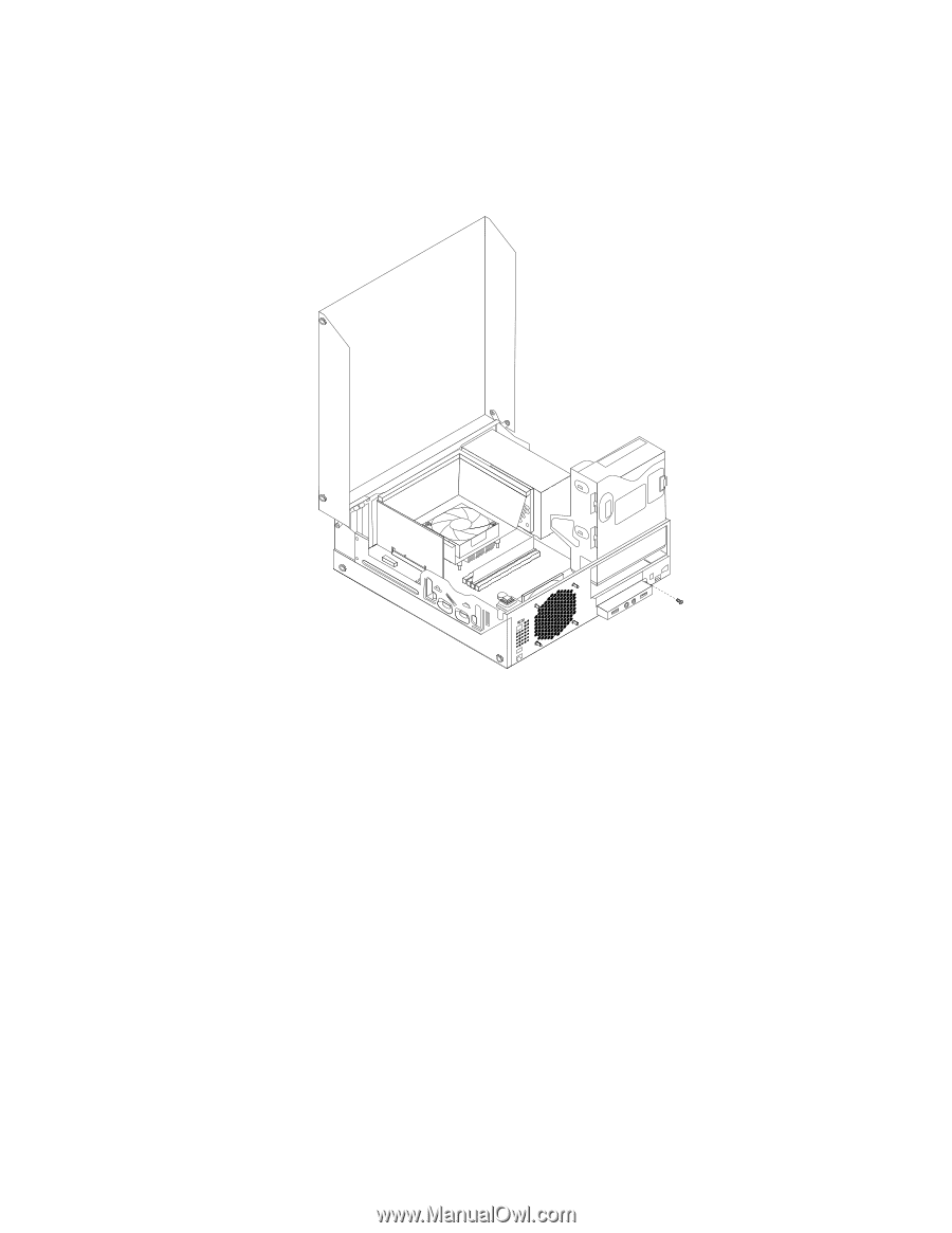
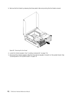
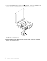
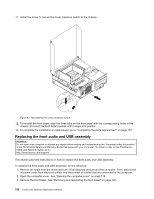
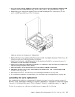
4. Pivot the optical drive bay upward and disconnect the front audio and USB assembly cables from the system board and note the cables routing. See "Locating parts on the system board" on page 76. 5. Remove the screw that secures the front audio and USB assembly bracket. Then remove the front audio and USB assembly bracket from the chassis. Figure 94. Removing the front audio and USB assembly 6. Remove the two screws that secure the front audio and USB assembly to its bracket. Then remove the failing front audio and USB assembly from the bracket. 7. Install a new front audio and USB assembly into the bracket and install the two screws to secure the front audio and USB assembly to the bracket. 8. Install the front audio and USB assembly bracket to the chassis and align the screw hole in the bracket with the corresponding hole in the chassis. 9. Install the screw to secure the front audio and USB assembly bracket to the chassis. 10. Reconnect the front USB and front audio cables to the system board. See "Locating parts on the system board" on page 76. 11. Reinstall the front bezel. See "Removing and reinstalling the front bezel" on page 120. 12. To complete the installation or replacement, go to "Completing the parts replacement" on page 157. Completing the parts replacement After completing the installation or replacement for all parts, you need to close the computer cover and reconnect cables. Depending on the parts you installed or replaced, you might need to confirm the updated information in the Setup Utility program. Refer to Chapter 6 "Using the Setup Utility program" on page 43. To close the computer cover and reconnect cables to your computer, do the following: Chapter 9. Replacing FRUs (Machine Types: 3120, 3122, 3126, and 3128.) 157
-
 1
1 -
2
-
3
-
4
-
5
-
6
-
7
-
8
-
9
-
10
-
11
-
12
-
13
-
14
-
15
-
16
-
17
-
18
-
19
-
20
-
21
-
22
-
23
-
24
-
25
-
26
-
27
-
28
-
29
-
30
-
31
-
32
-
33
-
34
-
35
-
36
-
37
-
38
-
39
-
40
-
41
-
42
-
43
-
44
-
45
-
46
-
47
-
48
-
49
-
50
-
51
-
52
-
53
-
54
-
55
-
56
-
57
-
58
-
59
-
60
-
61
-
62
-
63
-
64
-
65
-
66
-
67
-
68
-
69
-
70
-
71
-
72
-
73
-
74
-
75
-
76
-
77
-
78
-
79
-
80
-
81
-
82
-
83
-
84
-
85
-
86
-
87
-
88
-
89
-
90
-
91
-
92
-
93
-
94
-
95
-
96
-
97
-
98
-
99
-
100
-
101
-
102
-
103
-
104
-
105
-
106
-
107
-
108
-
109
-
110
-
111
-
112
-
113
-
114
-
115
-
116
-
117
-
118
-
119
-
120
-
121
-
122
-
123
-
124
-
125
-
126
-
127
-
128
-
129
-
130
-
131
-
132
-
133
-
134
-
135
-
136
-
137
-
138
-
139
-
140
-
141
-
142
-
143
-
144
-
145
-
146
-
147
-
148
-
149
-
150
-
151
-
152
-
153
-
154
-
155
-
 156
156 -
 157
157 -
 158
158 -
 159
159 -
 160
160 -
 161
161 -
 162
162 -
 163
163 -
 164
164 -
 165
165 -
 166
166 -
167
-
168
-
169
-
170
-
171
-
172
-
173
-
174
-
175
-
176
-
177
-
178
-
179
-
180
-
181
-
182
-
183
-
184
-
185
-
186
-
187
-
188
-
189
-
190
-
191
-
192
-
193
-
194
-
195
-
196
-
197
-
198
-
199
-
200
-
201
-
202
-
203
-
204
-
205
-
206
-
207
-
208
-
209
-
210
-
211
-
212
-
213
-
214
 |
 |