Lenovo ThinkCentre M76 Hardware Maintenance Manual for ThinkCentre M76 - Page 159
the corresponding hole in the chassis.,
 |
View all Lenovo ThinkCentre M76 manuals
Add to My Manuals
Save this manual to your list of manuals |
Page 159 highlights
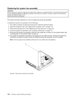
Figure 92. Installing the new internal speaker 9. Reconnect the internal speaker cable to the system board. See "Locating parts on the system board" on page 76. 10. Position the cover presence switch so that the screw hole in the cover presence switch is aligned with the corresponding hole in the chassis. Chapter 9. Replacing FRUs (Machine Types: 3120, 3122, 3126, and 3128.) 155
-
 1
1 -
2
-
3
-
4
-
5
-
6
-
7
-
8
-
9
-
10
-
11
-
12
-
13
-
14
-
15
-
16
-
17
-
18
-
19
-
20
-
21
-
22
-
23
-
24
-
25
-
26
-
27
-
28
-
29
-
30
-
31
-
32
-
33
-
34
-
35
-
36
-
37
-
38
-
39
-
40
-
41
-
42
-
43
-
44
-
45
-
46
-
47
-
48
-
49
-
50
-
51
-
52
-
53
-
54
-
55
-
56
-
57
-
58
-
59
-
60
-
61
-
62
-
63
-
64
-
65
-
66
-
67
-
68
-
69
-
70
-
71
-
72
-
73
-
74
-
75
-
76
-
77
-
78
-
79
-
80
-
81
-
82
-
83
-
84
-
85
-
86
-
87
-
88
-
89
-
90
-
91
-
92
-
93
-
94
-
95
-
96
-
97
-
98
-
99
-
100
-
101
-
102
-
103
-
104
-
105
-
106
-
107
-
108
-
109
-
110
-
111
-
112
-
113
-
114
-
115
-
116
-
117
-
118
-
119
-
120
-
121
-
122
-
123
-
124
-
125
-
126
-
127
-
128
-
129
-
130
-
131
-
132
-
133
-
134
-
135
-
136
-
137
-
138
-
139
-
140
-
141
-
142
-
143
-
144
-
145
-
146
-
147
-
148
-
149
-
150
-
151
-
152
-
153
-
 154
154 -
 155
155 -
 156
156 -
 157
157 -
 158
158 -
 159
159 -
 160
160 -
 161
161 -
 162
162 -
 163
163 -
 164
164 -
165
-
166
-
167
-
168
-
169
-
170
-
171
-
172
-
173
-
174
-
175
-
176
-
177
-
178
-
179
-
180
-
181
-
182
-
183
-
184
-
185
-
186
-
187
-
188
-
189
-
190
-
191
-
192
-
193
-
194
-
195
-
196
-
197
-
198
-
199
-
200
-
201
-
202
-
203
-
204
-
205
-
206
-
207
-
208
-
209
-
210
-
211
-
212
-
213
-
214
 |
 |
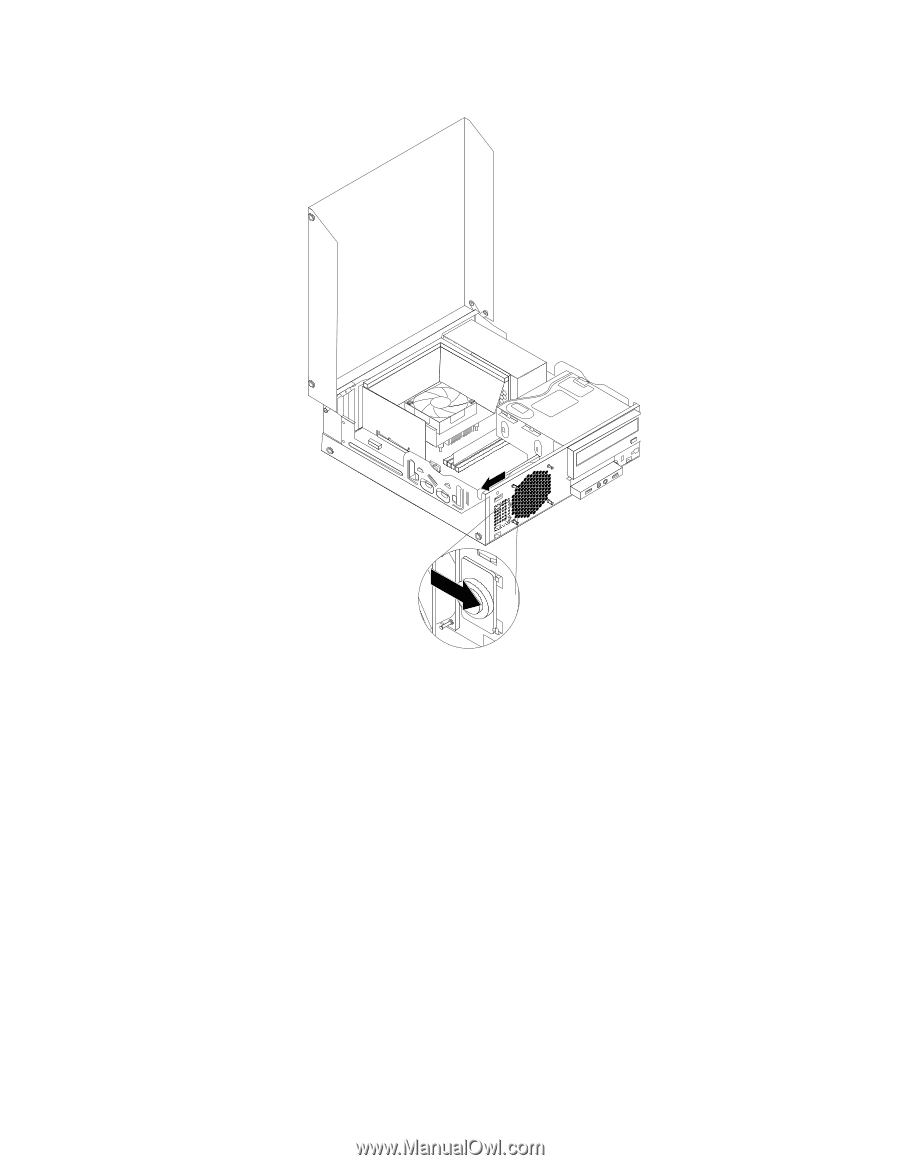
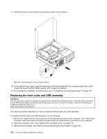
Figure 92. Installing the new internal speaker
9. Reconnect the internal speaker cable to the system board. See “Locating parts on the system board”
on page 76.
10. Position the cover presence switch so that the screw hole in the cover presence switch is aligned with
the corresponding hole in the chassis.
Chapter 9
.
Replacing FRUs (Machine Types: 3120, 3122, 3126, and 3128.)
155