Lenovo ThinkCentre M76 Hardware Maintenance Manual for ThinkCentre M76 - Page 150
Locate the system board and disconnect all cables connected to the system board. See Locating
 |
View all Lenovo ThinkCentre M76 manuals
Add to My Manuals
Save this manual to your list of manuals |
Page 150 highlights
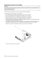
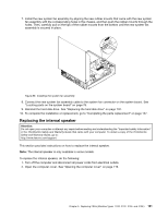
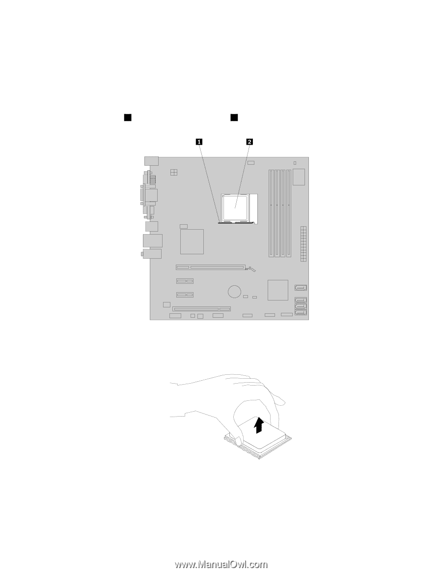
3. Locate the system board and disconnect all cables connected to the system board. See "Locating parts on the system board" on page 76. 4. Remove the heat sink and fan assembly with the fan duct. See "Replacing the heat sink and fan assembly" on page 137. Note: Do not let the thermal grease on the bottom of the heat sink and fan assembly get in contact with anything. 5. Lift the small handle 1 to release the microprocessor 2 secured on the system board. Figure 83. Accessing the microprocessor 6. Lift the microprocessor straight up and out of the microprocessor socket. Figure 84. Removing the microprocessor Notes: a. Your microprocessor and socket might look different from the one illustrated. 146 ThinkCentre Hardware Maintenance Manual
-
 1
1 -
2
-
3
-
4
-
5
-
6
-
7
-
8
-
9
-
10
-
11
-
12
-
13
-
14
-
15
-
16
-
17
-
18
-
19
-
20
-
21
-
22
-
23
-
24
-
25
-
26
-
27
-
28
-
29
-
30
-
31
-
32
-
33
-
34
-
35
-
36
-
37
-
38
-
39
-
40
-
41
-
42
-
43
-
44
-
45
-
46
-
47
-
48
-
49
-
50
-
51
-
52
-
53
-
54
-
55
-
56
-
57
-
58
-
59
-
60
-
61
-
62
-
63
-
64
-
65
-
66
-
67
-
68
-
69
-
70
-
71
-
72
-
73
-
74
-
75
-
76
-
77
-
78
-
79
-
80
-
81
-
82
-
83
-
84
-
85
-
86
-
87
-
88
-
89
-
90
-
91
-
92
-
93
-
94
-
95
-
96
-
97
-
98
-
99
-
100
-
101
-
102
-
103
-
104
-
105
-
106
-
107
-
108
-
109
-
110
-
111
-
112
-
113
-
114
-
115
-
116
-
117
-
118
-
119
-
120
-
121
-
122
-
123
-
124
-
125
-
126
-
127
-
128
-
129
-
130
-
131
-
132
-
133
-
134
-
135
-
136
-
137
-
138
-
139
-
140
-
141
-
142
-
143
-
144
-
 145
145 -
 146
146 -
 147
147 -
 148
148 -
 149
149 -
 150
150 -
 151
151 -
 152
152 -
 153
153 -
 154
154 -
 155
155 -
156
-
157
-
158
-
159
-
160
-
161
-
162
-
163
-
164
-
165
-
166
-
167
-
168
-
169
-
170
-
171
-
172
-
173
-
174
-
175
-
176
-
177
-
178
-
179
-
180
-
181
-
182
-
183
-
184
-
185
-
186
-
187
-
188
-
189
-
190
-
191
-
192
-
193
-
194
-
195
-
196
-
197
-
198
-
199
-
200
-
201
-
202
-
203
-
204
-
205
-
206
-
207
-
208
-
209
-
210
-
211
-
212
-
213
-
214
 |
 |
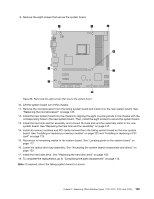
3. Locate the system board and disconnect all cables connected to the system board. See “Locating
parts on the system board” on page 76.
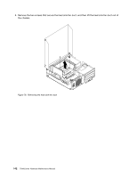
4. Remove the heat sink and fan assembly with the fan duct. See “Replacing the heat sink and fan
assembly” on page 137.
Note:
Do not let the thermal grease on the bottom of the heat sink and fan assembly get in contact
with anything.
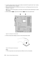
5. Lift the small handle
1
to release the microprocessor
2
secured on the system board.
Figure 83. Accessing the microprocessor
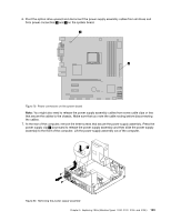
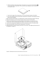
6. Lift the microprocessor straight up and out of the microprocessor socket.
Figure 84. Removing the microprocessor
Notes:
a.
Your microprocessor and socket might look different from the one illustrated.
146
ThinkCentre Hardware Maintenance Manual