Lenovo ThinkCentre M76 Hardware Maintenance Manual for ThinkCentre M76 - Page 153
Reconnect all remaining cables to the system board. See Locating parts on the system board
 |
View all Lenovo ThinkCentre M76 manuals
Add to My Manuals
Save this manual to your list of manuals |
Page 153 highlights
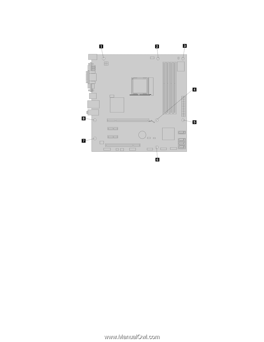
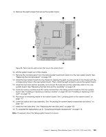
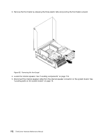
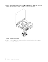
9. Remove the eight screws that secure the system board. Figure 86. Removing the eight screws that secure the system board 10. Lift the system board out of the chassis. 11. Remove the microprocessor from the failing system board and install it on the new system board. See "Replacing the microprocessor" on page 145. 12. Install the new system board into the chassis by aligning the eight mounting studs in the chassis with the corresponding holes in the new system board. Then, install the eight screws to secure the system board. 13. Install the heat sink and fan assembly and connect the heat sink and fan assembly cable to the new system board. See "Replacing the heat sink and fan assembly" on page 137. 14. Install all memory modules and PCI cards removed from the failing system board on the new system board. See "Installing or replacing a memory module" on page 123 and "Installing or replacing a PCI card" on page 124. 15. Reconnect all remaining cables to the system board. See "Locating parts on the system board" on page 117. 16. Lower the optical drive bay assembly. See "Accessing the system board components and drives" on page 122. 17. Install the hard disk drive. See "Replacing the hard disk drive" on page 132. 18. To complete the replacement, go to "Completing the parts replacement" on page 110. Note: If required, return the failing system board to Lenovo. Chapter 9. Replacing FRUs (Machine Types: 3120, 3122, 3126, and 3128.) 149
-
 1
1 -
2
-
3
-
4
-
5
-
6
-
7
-
8
-
9
-
10
-
11
-
12
-
13
-
14
-
15
-
16
-
17
-
18
-
19
-
20
-
21
-
22
-
23
-
24
-
25
-
26
-
27
-
28
-
29
-
30
-
31
-
32
-
33
-
34
-
35
-
36
-
37
-
38
-
39
-
40
-
41
-
42
-
43
-
44
-
45
-
46
-
47
-
48
-
49
-
50
-
51
-
52
-
53
-
54
-
55
-
56
-
57
-
58
-
59
-
60
-
61
-
62
-
63
-
64
-
65
-
66
-
67
-
68
-
69
-
70
-
71
-
72
-
73
-
74
-
75
-
76
-
77
-
78
-
79
-
80
-
81
-
82
-
83
-
84
-
85
-
86
-
87
-
88
-
89
-
90
-
91
-
92
-
93
-
94
-
95
-
96
-
97
-
98
-
99
-
100
-
101
-
102
-
103
-
104
-
105
-
106
-
107
-
108
-
109
-
110
-
111
-
112
-
113
-
114
-
115
-
116
-
117
-
118
-
119
-
120
-
121
-
122
-
123
-
124
-
125
-
126
-
127
-
128
-
129
-
130
-
131
-
132
-
133
-
134
-
135
-
136
-
137
-
138
-
139
-
140
-
141
-
142
-
143
-
144
-
145
-
146
-
147
-
 148
148 -
 149
149 -
 150
150 -
 151
151 -
 152
152 -
 153
153 -
 154
154 -
 155
155 -
 156
156 -
 157
157 -
 158
158 -
159
-
160
-
161
-
162
-
163
-
164
-
165
-
166
-
167
-
168
-
169
-
170
-
171
-
172
-
173
-
174
-
175
-
176
-
177
-
178
-
179
-
180
-
181
-
182
-
183
-
184
-
185
-
186
-
187
-
188
-
189
-
190
-
191
-
192
-
193
-
194
-
195
-
196
-
197
-
198
-
199
-
200
-
201
-
202
-
203
-
204
-
205
-
206
-
207
-
208
-
209
-
210
-
211
-
212
-
213
-
214
 |
 |