Lenovo ThinkCentre M76 Hardware Maintenance Manual for ThinkCentre M76 - Page 99
the plastic retention bracket.
 |
View all Lenovo ThinkCentre M76 manuals
Add to My Manuals
Save this manual to your list of manuals |
Page 99 highlights
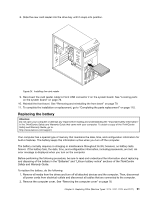
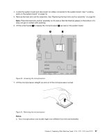
1. Turn off the computer and disconnect all power cords from electrical outlets. 2. Remove the computer cover. See "Removing the computer cover" on page 78. 3. Lay the computer on its side for easier access to the system board. 4. Locate the heat sink and fan assembly. See "Locating parts on the system board" on page 76. 5. Disconnect any cables that might prevent your access to the heat sink and fan assembly. 6. Disconnect the heat sink and fan assembly cable from the microprocessor fan connector on the system board. See "Locating parts on the system board" on page 76. 7. Pivot the handle 1 to release the heat sink and fan assembly clamp and then disengage the clamp from the plastic retention bracket. Figure 28. Removing the heat sink and fan assembly 8. Lift the failing heat sink and fan assembly off the system board. Notes: a. You might have to gently twist the heat sink and fan assembly to free it from the microprocessor. b. When handling the heat sink and fan assembly, do not touch the thermal grease on the bottom of it. Chapter 8. Replacing FRUs (Machine Types: 3114, 3121, 3123, and 3127.) 95
-
 1
1 -
2
-
3
-
4
-
5
-
6
-
7
-
8
-
9
-
10
-
11
-
12
-
13
-
14
-
15
-
16
-
17
-
18
-
19
-
20
-
21
-
22
-
23
-
24
-
25
-
26
-
27
-
28
-
29
-
30
-
31
-
32
-
33
-
34
-
35
-
36
-
37
-
38
-
39
-
40
-
41
-
42
-
43
-
44
-
45
-
46
-
47
-
48
-
49
-
50
-
51
-
52
-
53
-
54
-
55
-
56
-
57
-
58
-
59
-
60
-
61
-
62
-
63
-
64
-
65
-
66
-
67
-
68
-
69
-
70
-
71
-
72
-
73
-
74
-
75
-
76
-
77
-
78
-
79
-
80
-
81
-
82
-
83
-
84
-
85
-
86
-
87
-
88
-
89
-
90
-
91
-
92
-
93
-
 94
94 -
 95
95 -
 96
96 -
 97
97 -
 98
98 -
 99
99 -
 100
100 -
 101
101 -
 102
102 -
 103
103 -
 104
104 -
105
-
106
-
107
-
108
-
109
-
110
-
111
-
112
-
113
-
114
-
115
-
116
-
117
-
118
-
119
-
120
-
121
-
122
-
123
-
124
-
125
-
126
-
127
-
128
-
129
-
130
-
131
-
132
-
133
-
134
-
135
-
136
-
137
-
138
-
139
-
140
-
141
-
142
-
143
-
144
-
145
-
146
-
147
-
148
-
149
-
150
-
151
-
152
-
153
-
154
-
155
-
156
-
157
-
158
-
159
-
160
-
161
-
162
-
163
-
164
-
165
-
166
-
167
-
168
-
169
-
170
-
171
-
172
-
173
-
174
-
175
-
176
-
177
-
178
-
179
-
180
-
181
-
182
-
183
-
184
-
185
-
186
-
187
-
188
-
189
-
190
-
191
-
192
-
193
-
194
-
195
-
196
-
197
-
198
-
199
-
200
-
201
-
202
-
203
-
204
-
205
-
206
-
207
-
208
-
209
-
210
-
211
-
212
-
213
-
214
 |
 |
