Lenovo ThinkStation P300 (English) User Guide - Tower Form Factor - Page 18
Locating parts on the system board
 |
View all Lenovo ThinkStation P300 manuals
Add to My Manuals
Save this manual to your list of manuals |
Page 18 highlights
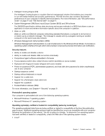
Locating parts on the system board The following illustration shows the locations of the parts on the system board. Figure 4. System board part locations 1 PS/2 keyboard and mouse connector 3 Battery 5 Microprocessor fan connector 7 Memory slot 2 (DIMM2) 9 Memory slot 4 (DIMM4) 11 Hard disk drive fan connector 13 14-pin power connector 15 SATA 3.0 connectors (4) 17 Front panel connector (for connecting LED indicators and the power button) 19 USB 2.0/card-reader connector 21 Clear CMOS/Recovery jumper 23 Internal speaker connector 25 PCI card slot 27 PCI Express x1 card slot 29 System fan connector 2 4-pin power connector 4 Microprocessor 6 Memory slot 1 (DIMM1) 8 Memory slot 3 (DIMM3) 10 Thermal sensor connector 12 4-pin SATA power connectors (2) 14 eSATA connector 16 Power fan connector 18 Front USB 3.0 connector 20 USB hardware disable header 22 Serial (COM2) connector 24 Front audio connector 26 PCI Express x16 card slot (negotiable link width x4, x1) 28 PCI Express x16 graphics card slot (graphics card available on some models) 30 Cover presence switch connector (intrusion switch connector) 6 ThinkStation P300 User Guide
-
 1
1 -
2
-
3
-
4
-
5
-
6
-
7
-
8
-
9
-
10
-
11
-
12
-
 13
13 -
 14
14 -
 15
15 -
 16
16 -
 17
17 -
 18
18 -
 19
19 -
 20
20 -
 21
21 -
 22
22 -
 23
23 -
24
-
25
-
26
-
27
-
28
-
29
-
30
-
31
-
32
-
33
-
34
-
35
-
36
-
37
-
38
-
39
-
40
-
41
-
42
-
43
-
44
-
45
-
46
-
47
-
48
-
49
-
50
-
51
-
52
-
53
-
54
-
55
-
56
-
57
-
58
-
59
-
60
-
61
-
62
-
63
-
64
-
65
-
66
-
67
-
68
-
69
-
70
-
71
-
72
-
73
-
74
-
75
-
76
-
77
-
78
-
79
-
80
-
81
-
82
-
83
-
84
-
85
-
86
-
87
-
88
-
89
-
90
-
91
-
92
-
93
-
94
-
95
-
96
-
97
-
98
-
99
-
100
-
101
-
102
-
103
-
104
-
105
-
106
-
107
-
108
-
109
-
110
-
111
-
112
-
113
-
114
-
115
-
116
-
117
-
118
-
119
-
120
-
121
-
122
-
123
-
124
-
125
-
126
-
127
-
128
-
129
-
130
-
131
-
132
-
133
-
134
-
135
-
136
-
137
-
138
-
139
-
140
-
141
-
142
-
143
-
144
-
145
-
146
-
147
-
148
-
149
-
150
 |
 |
