Netgear C6300 User Manual - Page 8
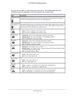
You can use the LEDs to verify status and connections. The following table lists - lights
 |
View all Netgear C6300 manuals
Add to My Manuals
Save this manual to your list of manuals |
Page 8 highlights
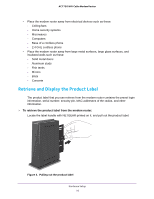
AC1750 WiFi Cable Modem Router You can use the LEDs to verify status and connections. The following table lists and describes each LED and button on the front panel of the modem router. LED Description WPS button with This button lets you use WPS to join the WiFi network without typing the WiFi password. LED The WPS LED blinks during this process and then lights solid. WiFi On/Off but- Pressing this button for two seconds turns the WiFi radios in the modem router on and off. If ton with LED this LED is lit, the WiFi radios are on. If this LED is off, the WiFi radios are turned off and you cannot use WiFi to connect to the modem router. Power Downstream Upstream Internet 2.4 GHz radio • Green. Power is supplied to the modem router. • Off. No power is supplied to the modem router. • Solid green. One or more downstream channels are locked. • Blinking green. The unit is scanning for a downstream channel. • Off. No downstream channel is locked. • Solid green. One or more upstream channels are locked. • Blinking green. The unit is scanning for an upstream channel. • Off. No upstream channel is locked. • Solid green. The modem router is online. • Blinking green. The modem router is synchronizing with the cable provider's cable modem termination system (CMTS). • Off. The modem router is offline. • Green. The 2.4 GHz radio is on. • Off. The 2.4 GHz radio is off. 5 GHz radio • Green. The 5 GHz radio is on. • Off. The 5 GHz radio is off. Ethernet USB • Green. A device is connected to an Ethernet port and powered on. • Off. No device is connected to an Ethernet port. • Green. A USB device is connected to the port on the back panel. • Off. No USB device is connected to the port on the back panel. Hardware Setup 8
-
 1
1 -
2
-
 3
3 -
 4
4 -
 5
5 -
 6
6 -
 7
7 -
 8
8 -
 9
9 -
 10
10 -
 11
11 -
 12
12 -
 13
13 -
14
-
15
-
16
-
17
-
18
-
19
-
20
-
21
-
22
-
23
-
24
-
25
-
26
-
27
-
28
-
29
-
30
-
31
-
32
-
33
-
34
-
35
-
36
-
37
-
38
-
39
-
40
-
41
-
42
-
43
-
44
-
45
-
46
-
47
-
48
-
49
-
50
-
51
-
52
-
53
-
54
-
55
-
56
-
57
-
58
-
59
-
60
-
61
-
62
-
63
-
64
-
65
-
66
-
67
-
68
-
69
-
70
-
71
-
72
-
73
-
74
-
75
-
76
-
77
-
78
-
79
-
80
-
81
-
82
-
83
-
84
-
85
-
86
-
87
-
88
-
89
-
90
-
91
-
92
-
93
-
94
-
95
-
96
-
97
-
98
 |
 |
