Optoma ZU1100 Manual - Page 93
∆Ho, Max. of ∆Hm, The calculation is based on 1/2 image width and 1/2 image height.
 |
View all Optoma ZU1100 manuals
Add to My Manuals
Save this manual to your list of manuals |
Page 93 highlights
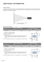
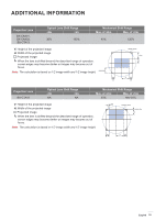
ADDITIONAL INFORMATION Projection Lens BX-CAA01, BX-CAA03, BX-CTA13 Optical Lens Shift Range ∆Ho ∆Vo 30% 100% Mechanical Shift Range Max. of ∆Hm Max. of ∆Vm 40% 120% V: Height of the projected image H: Width of the projected image Projected image When the lens is shifted beyond the described range of operation, screen edges may become darker or images may become out of focus. Note: The calculation is based on 1/2 image width and 1/2 image height. ∆Vm/∆Vo ∆Hm ∆Ho lmage circle ∆Vm V H ∆Hm ∆Ho Projection Lens BX-CTA16 Optical Lens Shift Range ∆Ho ∆Vo NA NA Mechanical Shift Range Max. of ∆Hm Max. of ∆Vm 20% NA/-20% V: Height of the projected image H: Width of the projected image Projected image When the lens is shifted beyond the described range of operation, screen edges may become darker or images may become out of focus. Note: The calculation is based on 1/2 image width and 1/2 image height. ∆Ho lmage circle ∆Vm/∆Vo V ∆Hm H ∆Hm English 93
-
 1
1 -
2
-
3
-
4
-
5
-
6
-
7
-
8
-
9
-
10
-
11
-
12
-
13
-
14
-
15
-
16
-
17
-
18
-
19
-
20
-
21
-
22
-
23
-
24
-
25
-
26
-
27
-
28
-
29
-
30
-
31
-
32
-
33
-
34
-
35
-
36
-
37
-
38
-
39
-
40
-
41
-
42
-
43
-
44
-
45
-
46
-
47
-
48
-
49
-
50
-
51
-
52
-
53
-
54
-
55
-
56
-
57
-
58
-
59
-
60
-
61
-
62
-
63
-
64
-
65
-
66
-
67
-
68
-
69
-
70
-
71
-
72
-
73
-
74
-
75
-
76
-
77
-
78
-
79
-
80
-
81
-
82
-
83
-
84
-
85
-
86
-
87
-
 88
88 -
 89
89 -
 90
90 -
 91
91 -
 92
92 -
 93
93 -
 94
94 -
 95
95 -
 96
96 -
 97
97 -
 98
98 -
99
-
100
-
101
 |
 |
