Panasonic AJHD1400 AJHD1400 User Guide - Page 37
BASIC, SYSTEM continued
 |
View all Panasonic AJHD1400 manuals
Add to My Manuals
Save this manual to your list of manuals |
Page 37 highlights
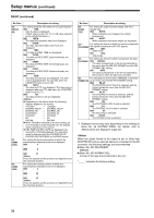
Setup menus (continued) SYSTEM (continued) BASIC No./Item Description of setting 25 SYSTEM FREQ 26*1 HD SYS H ADV For selecting the system frequency. For details, refer to "Procedure for shifting the system frequency" (page 31). 0000 59/60 : The 59.94 Hz or 60 Hz system frequency is selected. 0001 50i/25P : The 50 Hz or 25 PsF system frequency is selected. At this setting, the 1080/25 PsF format signals can be recorded and played back in the same way as with the 1080/50i format. 0002 23/24 : The 23.98 Hz or 24 Hz system frequency is selected. 0003 25(HD) : The 25 Hz system frequency is selected. However, black signals are output from the SD SDI output and analog composite connectors. 0004 25(SD) : The 25 Hz system frequency is selected. However, black signals are output from the HD SDI output and analog component connectors. 0005 50(HD) : The 50 Hz system frequency is selected. However, black signals are output from the SD SDI output and analog composite connectors. 0006 50(SD) : The 50 Hz system frequency is selected. However, black signals are output from the HD SDI output and analog component connectors. For selecting the output whose HD output phase is to be advanced by 90H in relation to the SD output. 0000 0H : Both the HD and SD signals are output in phase with the HD and SD REF output signals. 0001 90H : The HD signals are output at a phase advanced by 90H from the SD output signals. When the SD REF signal is input, the REF input and SD output are in-phase, and when the HD REF signal is input, the REF input and HD output are inphase. z The audio signals and TC signal are output in phase with the HD output. z With the 720p format, there is a phase difference of 120H between them. *1 Displayed menus may vary depending on the settings in menu No. 25 SYSTEM FREQ. For details, refer to "Menus which are displayed" (page 32). No./Item Description of setting 001 LOCAL ENA For setting the operable buttons on the front panel when the REMOTE/LOCAL switch is set to "REMOTE." 0000 DIS : None of the buttons can be operated. 0001 ST&EJ : Only the STOP and EJECT buttons can be operated. 0002 ENA1 : All of the buttons with the exception of COUNTER and RESET can be operated. 0003 ENA2 : All of the buttons can be operated. 002*1 TAPE TIMER For setting how the time is to be displayed on the CTL counter display. 0000 ±12h : 12-hour display 0001 24h : 24-hour display 003 For setting the remaining time on the tape for the REMAIN SEL respective connectors and the superimposed indications of the total length of the tape. 0000 OFF : No displays are superimposed. 0001 2L : The remaining tape time is displayed on the second line. 0002 1L : The remaining tape time is displayed on the first line. 0003 R/TTL : The remaining tape time is displayed on the first line and the total tape duration on the second line. The information will not be displayed when "2L" or "R/ TTL" is set and TIME is selected as the menu item No.006 DISPLAY SEL setting. 005 SUPER For setting the superimposing of the displays onto various connectors. 0000 OFF : The displays are superimposed onto none of the output connectors. 0001 CMPST : The displays are superimposed onto the analog composite output. 0002 CMPNT : The displays are superimposed onto the HD analog component output. 0003 SDSDI : The displays are superimposed onto SD SDI OUT. 0004 HDSDI : The displays are superimposed onto HD SDI OUT. 0005 CPS&SD : The displays are superimposed onto the analog composite output and SD SDI OUT. 0006 CPN&HD : The displays are superimposed onto the HD analog component output and HD SDI OUT. z The information will not be displayed when the SUPER switch is OFF. z 1394 output is according to Menu No. 899 DIF SUPER. z If the 23.98/24 Hz, 25 Hz (HD), or 50 Hz (HD) mode is selected in menu No. 25 SYSTEM FREQ, no super is displayed on the analog composite output and the SD SDI output. If the 25 Hz (SD) or 50 Hz (SD) mode is selected, no super is displayed on the analog component output and the HD SDI output. "_____" indicates the factory setting. 37
-
 1
1 -
2
-
3
-
4
-
5
-
6
-
7
-
8
-
9
-
10
-
11
-
12
-
13
-
14
-
15
-
16
-
17
-
18
-
19
-
20
-
21
-
22
-
23
-
24
-
25
-
26
-
27
-
28
-
29
-
30
-
31
-
 32
32 -
 33
33 -
 34
34 -
 35
35 -
 36
36 -
 37
37 -
 38
38 -
 39
39 -
 40
40 -
 41
41 -
 42
42 -
43
-
44
-
45
-
46
-
47
-
48
-
49
-
50
-
51
-
52
-
53
-
54
-
55
-
56
-
57
-
58
-
59
-
60
-
61
-
62
-
63
-
64
-
65
-
66
-
67
-
68
 |
 |
