Panasonic AJHD1400 AJHD1400 User Guide - Page 47
Video, Sdi In Mode
 |
View all Panasonic AJHD1400 manuals
Add to My Manuals
Save this manual to your list of manuals |
Page 47 highlights
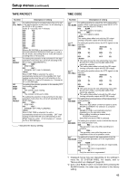
Setup menus (continued) VIDEO No./Item Description of setting 601*1 VIDEO INT SG For selecting the type of internal standard signals. 0000 100%CB : A 100% color bar signal is selected. 0001 75%CB : A 75% color bar signal is selected. 0002 SMPTE : An SMPTE color bar signal is selected. 0003 ARIB : An ARIB color bar signal is selected. 0004 BLACK : A black signal is selected. 602*1 For selecting how to process the serial input. SDI IN MODE 0000 DR_OFF : The 8 higher bits whose two lower bits have been rounded off are recorded. 0001 DR_ON : The dynamically rounded 8 higher bit signal is recorded. 603 V-MUTE SEL For setting whether to mute the video output signal when a blank part of the tape is detected during playback. 0000 N-MUTE : The video output signal is not muted. (It is frozen.) 0001 GRAY : The video output signal is muted and turned gray. 0002 BLACK : The video output signal is muted and turned black. 0003 NOISE : The video output signal is muted and turned into noise. 604 For selecting the freeze mode of the still pictures and FREEZE SEL the slow play mode. 0000 FIELD : Field freeze, field slow 0001 FRAME : Frame freeze, frame slow For IEEE 1394 digital output, if format conversion is not executed, the frames may freeze or slow down regardless of the settings in this item. 615*1 V OUT SEL For selecting what signals are to be output from the VIDEO OUT1 output connector. 0000 CMPNT : The HD component signals are output. 0001 CMPST : Composite signals are output. When the CMPST is selected, the Pb and Pr of the analog HD component signals are muted. 619*1 V_FILTER This is used to select the method to process the images using the vertical filter during down- conversion. 0000 FIELD : The images are processed by field basis. 0001 FRAME : The images are processed by frame basis. When "FRAME" has been selected, the resolution is improved, but the images may flicker. 620*1 DOWNCON MODE For setting the image processing during down- conversion. 0000 FIT_V : Side cut mode 0001 FIT_H : Letter-box mode 0002 FIT_HV : Squeeze mode No./Item Description of setting 621*1 UPCONV MODE 626*1 D/C ENH H 627*1 D/C ENH V 628*1 U/C ENH H 629*1 U/C ENH V 630*1 1080i > HD_OUT 632*1 720p> HD_OUT 636*1 SD > HD_OUT 650 STYLE For setting the image processing during up- conversion. 0000 FIT_V : Side panel mode 0001 FIT_H : Top and bottom cut-off in vertical direction 0002 FIT_HV : Stretch mode For enhancing the horizontal outlines during down- conversion. 0000 0dB 0001 +1dB For enhancing the vertical outlines during down- conversion. 0000 0dB 0001 +1dB For enhancing the horizontal outlines during up- conversion. 0000 0dB 0001 +1dB For enhancing the vertical outlines during up- conversion. 0000 0dB 0001 +1dB For selecting the HD output signal format during 1080i tape playback or in the 1080i EE mode. 0000 1080i 0001 720p This item's setting cannot be changed while a tape is being recorded or while the recording pause mode is established. For selecting the HD output signal format during 720p tape playback or in the 720p EE mode. 0000 1080i 0001 720p This item's setting cannot be changed while a tape is being recorded or while the recording pause mode is established. For selecting the HD output signal format during SD tape (DVCPRO50, DVCPRO, DV or DVCAM) playback. 0000 1080i 0001 720p 0000 CMPNT : Level adjustment mode for the component style 0001 CMPST : Level adjustment mode for the composite style *1 Displayed menus may vary depending on the settings in menu No. 25 SYSTEM FREQ. For details, refer to "Menus which are displayed" (page 32). "_____" indicates the factory setting. 47
-
 1
1 -
2
-
3
-
4
-
5
-
6
-
7
-
8
-
9
-
10
-
11
-
12
-
13
-
14
-
15
-
16
-
17
-
18
-
19
-
20
-
21
-
22
-
23
-
24
-
25
-
26
-
27
-
28
-
29
-
30
-
31
-
32
-
33
-
34
-
35
-
36
-
37
-
38
-
39
-
40
-
41
-
 42
42 -
 43
43 -
 44
44 -
 45
45 -
 46
46 -
 47
47 -
 48
48 -
 49
49 -
 50
50 -
 51
51 -
 52
52 -
53
-
54
-
55
-
56
-
57
-
58
-
59
-
60
-
61
-
62
-
63
-
64
-
65
-
66
-
67
-
68
 |
 |
