Panasonic AJHD1400 AJHD1400 User Guide - Page 49
AJ-HD1400P
 |
View all Panasonic AJHD1400 manuals
Add to My Manuals
Save this manual to your list of manuals |
Page 49 highlights
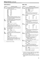
Setup menus (continued) VIDEO (continued) No./Item Description of setting 665 For adjusting the setup ( or black) level of the HD SDI, SETUP LVL analog component output, SD SDI output and analog (AJ-HD1400P) composite output. (-10 o to +10 o) 50 -10% BK LVL (AJ-HD1400E) : 150 : : 0.0% : 250 +10.0% This setting takes effect when "CMPST" has been selected as the menu item No.650 setting. 676*1 BLK CLIP For setting whether to clip what is below the pedestal level for the Y (luminance) signal of composite output and SD SDI output. 0000 OFF : What is below the pedestal level is not clipped. 0001 ON : What is below the pedestal level is clipped. 680*1 CC (F1) BLANK*DW For selecting ON or OFF for the closed caption signal in the first field. 0000 BLANK : Forced blanking 0001 THRU : No blanking 681*1 CC (F2) BLANK*DW For selecting ON or OFF for the closed caption signal in the second field. 0000 BLANK : Forced blanking 0001 THRU : No blanking 682*1 This selects the composite output signal in HD mode. VO SETUP 0000 THRU : (HD)*UP The signal is output with no setup added. 0001 ADD22L : (AJ-HD1400P) The signal is output from line 22 with a 7.5% setup added. 0002 ADD21L : The signal is output from line 21 with a 7.5% setup added. 0003 ADD20L : The signal is output from line 20 with a 7.5% setup added. 683*1 This selects the composite output signal in SD mode. VO SETUP 0000 THRU : (SD)*DW The signal is output with no setup added. 0001 ADD22L : (AJ-HD1400P) The signal is output from line 22 with a 7.5% setup added. 0002 ADD21L : The signal is output from line 21 with a 7.5% setup added. 00023 ADD20L : The signal is output from line 20 with a 7.5% setup added. 684*1 For setting whether to superimpose EDH onto the SD EDH (SD)*DW SDI output. 0000 OFF : EDH is not superimposed. 0001 ON : EDH is superimposed. 685*1 ESR MODE (SD)*DW For selecting the mode of the edge subcarrier reduction (ESR) operation in the playback circuit. 0000 OFF : ESR is forcibly turned off. 0001 AUTO : ESR is automatically set to ON or OFF depending on the unitÅfs operation. No./Item Description of setting 686*1 CCR MODE (SD)*DW For selecting the cross color processing during playback. 0000 OFF : The cross color is output as is. 0001 ON : The cross color can be reduced. 687*1 SDI INDEX 0*DW For selecting whether to superimpose the VIDEO INDEX signal on the SD SDI output signal. 0000 OFF : The VIDEO INDEX signal is not superimposed on the SD SDI output signal. 0001 ON : The VIDEO INDEX signal is superimposed on the SD SDI output signal. 689*1 This is used to select the method to process the COMP MODE image compression during recording. 0000 NORMAL : The images are recorded using the regular compression processing. 0001 DARK : The images are recorded while minimizing the compressed image distortion which arises in the dark areas below about 10 IRE (70 mV). z This setting is valid when recording in the 720p mode. z When "DARK" has been selected, the COMP lamp lights. 690*1 UMID REC This selects whether or not to record the UMID information on the tape. 0000 OFF : UMID information is not recorded on the tape. 0001 ON : The UMID set in menu No. 691 UMID GEN is recorded. If no Basic UMID is available in the input signals, a Basic UMID of the unit, which is newly generated, is recorded. UMID information cannot be rewritten in this unit. 691*1 UMID GEN This selects a UMID that is recorded when menu No. 690 UMID REC is turned "ON". 0000 INT : Newly created basic UMID information of this unit is always recorded. 0001 EXT : The UMID information of the input signals is recorded. If no UMID is available in the input signals, a Basic UMID of the unit, which is newly generated, is recorded. The source pack (of the UMID information) of the input signal will be recorded on the tape, regardless of this menu's setting. *1 Displayed menus may vary depending on the settings in menu No. 25 SYSTEM FREQ. For details, refer to "Menus which are displayed" (page 32). *UP: With HD output (HD tape playback or up-converted output) *DW: With SD output (SD tape playback or down-converted output) "_____" indicates the factory setting. 49
-
 1
1 -
2
-
3
-
4
-
5
-
6
-
7
-
8
-
9
-
10
-
11
-
12
-
13
-
14
-
15
-
16
-
17
-
18
-
19
-
20
-
21
-
22
-
23
-
24
-
25
-
26
-
27
-
28
-
29
-
30
-
31
-
32
-
33
-
34
-
35
-
36
-
37
-
38
-
39
-
40
-
41
-
42
-
43
-
 44
44 -
 45
45 -
 46
46 -
 47
47 -
 48
48 -
 49
49 -
 50
50 -
 51
51 -
 52
52 -
 53
53 -
 54
54 -
55
-
56
-
57
-
58
-
59
-
60
-
61
-
62
-
63
-
64
-
65
-
66
-
67
-
68
 |
 |
