Panasonic AV-HS410 Operating Instructions Advanced - Page 103
Setting the crosspoints, 3-2-1. Assigning signals to the crosspoints
 |
View all Panasonic AV-HS410 manuals
Add to My Manuals
Save this manual to your list of manuals |
Page 103 highlights
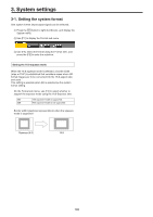
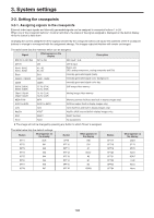
3. System settings 3-2. Setting the crosspoints 3-2-1. Assigning signals to the crosspoints External video input signals and internally generated signals can be assigned to crosspoint buttons 1 to 24. When one of the crosspoint buttons 1 to 24 is held down, the status of the signal assigned is displayed on the built-in display while the button is held down. Changing the current assignment of the signals selected by the crosspoint buttons will cause the positions of the lit crosspoint buttons to change to correspond with the assignment change. The images output at this time will remain unchanged. The table below lists the materials which can be assigned. Signal What appears on the display Description SDI IN1 to SDI IN8 IN1 to IN8 SDI input 1 to 8 DVI IN IN-A1, IN-A2, IN-B1, IN-B2 DVI A1, A2, B1, B2 DVI-D input Option slot (SDI, analog component, analog composite and DVI) Black CBGD1, CBGD2 BLK CBD1, CBD2 Internally generated signal (black) Internally generated signal (color background) CBAR CBAR Internally generated signal (color bar) Still1V, Still1K, Still2V, Still2K ST1V, ST1K, ST2V, ST2K Still image video memory Clip1V, Clip1K, Clip2V, Clip2K CL1V, CL1K, CL2V, CL2K Moving image video memory MEM-PVW MPV Memory preview (AUX bus and built-in display images only) AUX1 to AUX4 AUX1 to AUX4 AUX bus output (built-in display images only) CLN CLN CLN (AUX bus and built-in display images only) KeyOut KOUT KeyOut (AUX bus and built-in display images only) Shift SHIFT SHIFT function None None No assignment ppThe image will not be changed by pressing any button to which "None" is assigned. The table below lists the default settings. Button What appears on the display XPT1 BLK XPT2 IN1 XPT3 IN2 XPT4 IN3 XPT5 IN4 XPT6 IN5 XPT7 IN6 XPT8 IN7 Button XPT9 XPT10 XPT11 XPT12 XPT13 XPT14 XPT15 XPT16 What appears on the display IN8 DVI A1 None A2 B1 B2 CBAR Button XPT17 XPT18 XPT19 XPT20 XPT21 XPT22 XPT23 XPT24 What appears on the display CBD1 ST1V ST2V None KOUT CLN None None 103
-
 1
1 -
2
-
3
-
4
-
5
-
6
-
7
-
8
-
9
-
10
-
11
-
12
-
13
-
14
-
15
-
16
-
17
-
18
-
19
-
20
-
21
-
22
-
23
-
24
-
25
-
26
-
27
-
28
-
29
-
30
-
31
-
32
-
33
-
34
-
35
-
36
-
37
-
38
-
39
-
40
-
41
-
42
-
43
-
44
-
45
-
46
-
47
-
48
-
49
-
50
-
51
-
52
-
53
-
54
-
55
-
56
-
57
-
58
-
59
-
60
-
61
-
62
-
63
-
64
-
65
-
66
-
67
-
68
-
69
-
70
-
71
-
72
-
73
-
74
-
75
-
76
-
77
-
78
-
79
-
80
-
81
-
82
-
83
-
84
-
85
-
86
-
87
-
88
-
89
-
90
-
91
-
92
-
93
-
94
-
95
-
96
-
97
-
 98
98 -
 99
99 -
 100
100 -
 101
101 -
 102
102 -
 103
103 -
 104
104 -
 105
105 -
 106
106 -
 107
107 -
 108
108 -
109
-
110
-
111
-
112
-
113
-
114
-
115
-
116
-
117
-
118
-
119
-
120
-
121
-
122
-
123
-
124
-
125
-
126
-
127
-
128
-
129
-
130
-
131
-
132
-
133
-
134
-
135
-
136
-
137
-
138
-
139
-
140
-
141
-
142
-
143
-
144
-
145
-
146
 |
 |
