Panasonic AV-HS410 Operating Instructions Advanced - Page 75
Input connector, Setting menu and numbers of s in this manual, Delay, Freeze, Converter, Video
 |
View all Panasonic AV-HS410 manuals
Add to My Manuals
Save this manual to your list of manuals |
Page 75 highlights
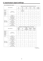
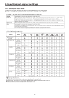
2. Input/output signal settings Input connector SDI IN1 to SDI IN4 SDI IN5, SDI IN6 SDI IN7, SDI IN8 DVI IN Option slot IN A1, IN A2, IN B1, IN B2 Standard SDI input 8 lines Standard DVI-D input 1 line AV-HS04M1 SDI input 2 lines AV-HS04M2 Analog component input 2 lines AV-HS04M3 DVI-I input 2 lines AV-HS04M6 Analog composite input 2 lines AV-HS04M8 DVI-D input 2 lines Input connector SDI IN1 to SDI IN4 SDI IN5, SDI IN6 SDI IN7, SDI IN8 DVI IN Option slot IN A1, IN A2, IN B1, IN B2 Standard SDI input 8 lines Standard DVI-D input 1 line AV-HS04M1 SDI input 2 lines AV-HS04M2 Analog component input 2 lines AV-HS04M3 DVI-I input 2 lines AV-HS04M6 Analog composite input 2 lines AV-HS04M8 DVI-D input 2 lines FS 2-1-1 Setting menu and numbers of sections in this manual Mode Delay Freeze Name 2-1-2 Only Dot by Dot selectable 2-1-3 - 2-1-4 2-1-5 - Up Converter 2-1-6 - - - - - - - - - - - - - - - Setting menu and numbers of sections in this manual Video Process (SDI) Gain Video Process (Composite) DVI Input (Digital) DVI Input (Analog) 2-1-7 2-1-8 2-1-9 2-1-10 2-1-10 - - - - - - - - - - - - - - - - - - - - - - - - - - - - - - - - - - - : Can be set. -: Cannot be set. 75
-
 1
1 -
2
-
3
-
4
-
5
-
6
-
7
-
8
-
9
-
10
-
11
-
12
-
13
-
14
-
15
-
16
-
17
-
18
-
19
-
20
-
21
-
22
-
23
-
24
-
25
-
26
-
27
-
28
-
29
-
30
-
31
-
32
-
33
-
34
-
35
-
36
-
37
-
38
-
39
-
40
-
41
-
42
-
43
-
44
-
45
-
46
-
47
-
48
-
49
-
50
-
51
-
52
-
53
-
54
-
55
-
56
-
57
-
58
-
59
-
60
-
61
-
62
-
63
-
64
-
65
-
66
-
67
-
68
-
69
-
 70
70 -
 71
71 -
 72
72 -
 73
73 -
 74
74 -
 75
75 -
 76
76 -
 77
77 -
 78
78 -
 79
79 -
 80
80 -
81
-
82
-
83
-
84
-
85
-
86
-
87
-
88
-
89
-
90
-
91
-
92
-
93
-
94
-
95
-
96
-
97
-
98
-
99
-
100
-
101
-
102
-
103
-
104
-
105
-
106
-
107
-
108
-
109
-
110
-
111
-
112
-
113
-
114
-
115
-
116
-
117
-
118
-
119
-
120
-
121
-
122
-
123
-
124
-
125
-
126
-
127
-
128
-
129
-
130
-
131
-
132
-
133
-
134
-
135
-
136
-
137
-
138
-
139
-
140
-
141
-
142
-
143
-
144
-
145
-
146
 |
 |
