Panasonic AV-HS410 Operating Instructions Advanced - Page 29
PinP (picture in picture), 1-4-1. Selecting the PinP channel and material
 |
View all Panasonic AV-HS410 manuals
Add to My Manuals
Save this manual to your list of manuals |
Page 29 highlights
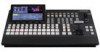
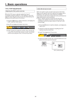
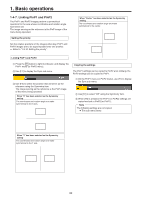
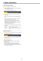
1. Basic operations 1-4. PinP (picture in picture) Another image can be combined with the background image. This unit supports two PinP channels. 1-4-1. Selecting the PinP channel and material Press the [PinP1] button (or [PinP2] button) among the AUX bus selector buttons. When the [PinP1] button (or [PinP2] button) is lit, the PinP1 menu (or PinP2 menu) is displayed on the built-in display. The state in which the PinP1 materials (or PinP2 materials) are selected is now established for the AUX bus crosspoint buttons. The selected AUX bus crosspoint button lights in amber. (It will light in red if the selected signal is a PGM output signal.) KEY PinP1 PinP2 DSK AUX1 AUX2 AMBER : FILL / GREEN : SOURCE AUX BUS DELEGATION AUX3 AUX4 DISP AUX MV PVW PGM AUX/DISP SOURCE SHIFT 1-4-2. Transition between PinP materials When a PinP bus material has been selected, the effect to be produced when images are switched can be executed as a MIX transition. (Bus transition function) pp When one material set to the Dot by Dot mode and another material have been switched, cut switching where the images change in an instant is performed. 1 Press the t button to light its indicator, and display the Time menu. 2 Use [F1] to display the PinP1 BUS Trans sub menu (or PinP2 BUS Trans sub menu). 3 Use [F3] and [F4] to set the transition time. 4 Use [F5] to set enable or disable for the bus transition function. Enable Disable Enable Disable While the transition is underway, the indicator of the transition source button lights, and the indicator of the transition destination button blinks. When the transition is completed, the indicator of the transition source button goes off, and the indicator of the transition destination button lights. When another signal has been selected while a transition is underway, the processing for the transition will continue from the interim point. 29
-
 1
1 -
2
-
3
-
4
-
5
-
6
-
7
-
8
-
9
-
10
-
11
-
12
-
13
-
14
-
15
-
16
-
17
-
18
-
19
-
20
-
21
-
22
-
23
-
 24
24 -
 25
25 -
 26
26 -
 27
27 -
 28
28 -
 29
29 -
 30
30 -
 31
31 -
 32
32 -
 33
33 -
 34
34 -
35
-
36
-
37
-
38
-
39
-
40
-
41
-
42
-
43
-
44
-
45
-
46
-
47
-
48
-
49
-
50
-
51
-
52
-
53
-
54
-
55
-
56
-
57
-
58
-
59
-
60
-
61
-
62
-
63
-
64
-
65
-
66
-
67
-
68
-
69
-
70
-
71
-
72
-
73
-
74
-
75
-
76
-
77
-
78
-
79
-
80
-
81
-
82
-
83
-
84
-
85
-
86
-
87
-
88
-
89
-
90
-
91
-
92
-
93
-
94
-
95
-
96
-
97
-
98
-
99
-
100
-
101
-
102
-
103
-
104
-
105
-
106
-
107
-
108
-
109
-
110
-
111
-
112
-
113
-
114
-
115
-
116
-
117
-
118
-
119
-
120
-
121
-
122
-
123
-
124
-
125
-
126
-
127
-
128
-
129
-
130
-
131
-
132
-
133
-
134
-
135
-
136
-
137
-
138
-
139
-
140
-
141
-
142
-
143
-
144
-
145
-
146
 |
 |
