Panasonic AV-HS410 Operating Instructions Advanced - Page 89
Assigning the output signals, 2-2-2. Setting the SDI output color range
 |
View all Panasonic AV-HS410 manuals
Add to My Manuals
Save this manual to your list of manuals |
Page 89 highlights
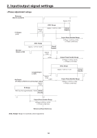
2. Input/output signal settings 2-2-1. Assigning the output signals The output signals can be assigned to the SDI OUT1 to SDI OUT5 connectors and DVI OUT connector. 1 On the Output sub menu, use [F2] to select the output to be set using the Select item. Refer to "2-2. Output signal settings". 2 Use [F1] to display the Assign sub menu. Assigning the CLN signal Set KEYCLN or DSKCLN as the CLN output. 1 Press the s button to light its indicator, and display the Config menu. 2 Use [F1] to display the Assign sub menu. 3 Use [F2] to set the type of output signal using the Source item. PGM PVW AUX1 to 4 CLN MV KeyOut MEM-PVW An image provided with the wipe, mix, key, downstream key or other effect is output at the switcher's main line output. This is the preview output that enables the next operation to be checked before it is executed. The signals selected by the 4 lines of AUX buses (AUX1 to AUX4) are output. The clean signal (the image resulting when the key, downstream key or other effect has been removed from the PGM signal) is output. Refer to "Assigning the CLN signal". The multi view display signals are output. Multiple input signals and output signals are reduced in size and output to one screen. The key signal is output. In the memory preview mode, the shot memory and event memory effects are output to preview. 4 Use [F3] to set the output mode using the Mode item. Normal Down Convert (downconverter) The same signals as the system format signals are output. This can be selected when the SDI output board (option: AV-HS04M7) has been connected. When the system format is 1080/59.94i or 720/59.94p, the signals are output in the 480/59.94i format. When the system format is 1080/50i or 720/50p, the signals are output in the 576/50i format. When the system format is SD (480/59.94i or 576/50i), this setting cannot be selected. 3 Use [F3] to select the type of output signal using the CLN item. Key DSK The PGM signals minus the key effects are output. The Key, PinP1, PinP2 and DSK effects are not added. The PGM signal minus the downstream key effects are output. 2-2-2. Setting the SDI output color range The color range can be set for the SDI output signal images. pp The same setting applies to all the SDI output signals. 1 On the Output sub menu, use [F5] to set the color range using the SDI Limit item. Refer to "2-2. Output signal settings". Off The color range is not restricted. 108 The amplitude level of the colors (R, G and B) is restricted to 0 % - 108 %. 104 The amplitude level of the colors (R, G and B) is restricted to 0 % - 104 %. 100 The amplitude level of the colors (R, G and B) is restricted to 0 % - 100 %. 89
-
 1
1 -
2
-
3
-
4
-
5
-
6
-
7
-
8
-
9
-
10
-
11
-
12
-
13
-
14
-
15
-
16
-
17
-
18
-
19
-
20
-
21
-
22
-
23
-
24
-
25
-
26
-
27
-
28
-
29
-
30
-
31
-
32
-
33
-
34
-
35
-
36
-
37
-
38
-
39
-
40
-
41
-
42
-
43
-
44
-
45
-
46
-
47
-
48
-
49
-
50
-
51
-
52
-
53
-
54
-
55
-
56
-
57
-
58
-
59
-
60
-
61
-
62
-
63
-
64
-
65
-
66
-
67
-
68
-
69
-
70
-
71
-
72
-
73
-
74
-
75
-
76
-
77
-
78
-
79
-
80
-
81
-
82
-
83
-
 84
84 -
 85
85 -
 86
86 -
 87
87 -
 88
88 -
 89
89 -
 90
90 -
 91
91 -
 92
92 -
 93
93 -
 94
94 -
95
-
96
-
97
-
98
-
99
-
100
-
101
-
102
-
103
-
104
-
105
-
106
-
107
-
108
-
109
-
110
-
111
-
112
-
113
-
114
-
115
-
116
-
117
-
118
-
119
-
120
-
121
-
122
-
123
-
124
-
125
-
126
-
127
-
128
-
129
-
130
-
131
-
132
-
133
-
134
-
135
-
136
-
137
-
138
-
139
-
140
-
141
-
142
-
143
-
144
-
145
-
146
 |
 |
