Pioneer DVR-520H-S Owner's Manual - Page 15
Connecting up, Easy connections
 |
View all Pioneer DVR-520H-S manuals
Add to My Manuals
Save this manual to your list of manuals |
Page 15 highlights
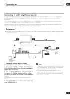
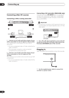
Connecting up 02 Easy connections The setup described here is a basic configuration that allows you to record TV programs on both this recorder and your VCR. When watching recordings from this recorder, set your TV to input 1; switch to input 2 to watch a video playing in the VCR. Important • This recorder is equipped with copy protection technology. Do not connect this recorder to your TV via a VCR (or your VCR via this recorder) using AV cables, as the picture from this recorder will not appear properly on your TV. • Before making or changing any rear panel connections, make sure that all components are switched off and unplugged from the wall outlet. A/V IN 2 TV 5 A/V OUT A/V IN 1 VHF/UHF IN 3 VHF/UHF 4 OUT VCR VHF/UHF IN 2 OUT IN VHF/UHF OUTPUT 1 R L R L INPUT 1/ AUTO START REC Y PB PR COMPONENT VIDEO OUT AUDIO VIDEO S-VIDEO OUTPUT 2 AUDIO VIDEO INPUT 3 S-VIDEO IN OPTICAL CONTROL DIGITAL OUT AC IN 1 Antenna/cable TV wall outlet 1 Connect your TV antenna/cable TV outlet to the VHF/UHF IN jack on this recorder. 2 Use an RF antenna cable (one is supplied) to connect the VHF/UHF OUT jack on this recorder to the antenna input on your VCR. • If you are not connecting a VCR in the chain, connect this recorder directly to your TV and skip the next step. 3 Use an RF antenna cable to connect the antenna output on your VCR to the antenna input on your TV. 4 Connect the AUDIO and VIDEO OUTPUT jacks (1 or 2) to a set of audio/video inputs on your TV. Use the supplied three-pin audio/video cable. It is colorcoded to help you match them up (red/white for the right/ left audio connections and yellow for video in/outs). Make sure you match up the left and right outputs with their corresponding inputs for correct stereo sound. 5 Connect your VCR to your TV (A/V IN 2 above) using a set of audio and video cables. Note • See the following page if you want to use S-video or component video cables for the video connection. 15 En
-
 1
1 -
2
-
3
-
4
-
5
-
6
-
7
-
8
-
9
-
 10
10 -
 11
11 -
 12
12 -
 13
13 -
 14
14 -
 15
15 -
 16
16 -
 17
17 -
 18
18 -
 19
19 -
 20
20 -
21
-
22
-
23
-
24
-
25
-
26
-
27
-
28
-
29
-
30
-
31
-
32
-
33
-
34
-
35
-
36
-
37
-
38
-
39
-
40
-
41
-
42
-
43
-
44
-
45
-
46
-
47
-
48
-
49
-
50
-
51
-
52
-
53
-
54
-
55
-
56
-
57
-
58
-
59
-
60
-
61
-
62
-
63
-
64
-
65
-
66
-
67
-
68
-
69
-
70
-
71
-
72
-
73
-
74
-
75
-
76
-
77
-
78
-
79
-
80
-
81
-
82
-
83
-
84
-
85
-
86
-
87
-
88
-
89
-
90
-
91
-
92
-
93
-
94
-
95
-
96
-
97
-
98
-
99
-
100
-
101
-
102
-
103
-
104
-
105
-
106
-
107
-
108
-
109
-
110
-
111
-
112
-
113
-
114
-
115
-
116
-
117
-
118
-
119
-
120
-
121
 |
 |
