Pioneer DVR-520H-S Owner's Manual - Page 17
Connecting up, Connecting to a cable box or satellite receiver 1
 |
View all Pioneer DVR-520H-S manuals
Add to My Manuals
Save this manual to your list of manuals |
Page 17 highlights
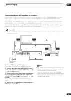
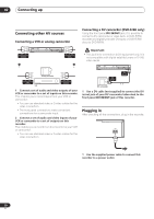
Connecting up 02 Connecting to a cable box or satellite receiver (1) If you are using a cable box or satellite receiver with only a few scrambled channels, follow the setup on this page. If many or all the channels are scrambled, we recommend using the setup on the following page. Using the setup on this page you can: • Record unscrambled channels by selecting them on this recorder. • Record scrambled channels by selecting them on the cable box/satellite tuner and using the Auto Start Recording feature (see Automatic recording from a satellite tuner on page 54). • Watch one channel while recording another. Important • Do not connect this recorder 'through' your VCR, satellite receiver or cable box. Always connect each component directly to your TV or AV amp/receiver. A/V IN 1 TV VHF/UHF IN 1 2 VHF/UHF OUT Cable box/ Satellite receiver VHF/UHF IN A/V OUT 3 1 OUT IN VHF/UHF OUTPUT 1 R L R L INPUT 1/ AUTO START REC Y PB PR COMPONENT VIDEO OUT AUDIO VIDEO S-VIDEO OUTPUT 2 AUDIO VIDEO INPUT 3 S-VIDEO IN OPTICAL CONTROL DIGITAL OUT AC IN 1 Antenna/cable TV wall outlet 1 Connect RF antenna cables as shown. This enables you to watch and record TV channels. 2 Connect the AUDIO and VIDEO OUTPUT jacks (1 or 2) on this recorder to a set of audio/video inputs on your TV using a set of A/V cables (as supplied). This enables you to watch the output from this recorder. 3 Connect the audio/video output of your cable box/satellite tuner to the INPUT 1/AUTO START REC jacks on this recorder using a set of A/V cables. This enables you to record scrambled TV channels. Note The diagram shows standard video connections, but you can alternatively use the S-video or component video connections if they're available. 17 En
-
 1
1 -
2
-
3
-
4
-
5
-
6
-
7
-
8
-
9
-
10
-
11
-
 12
12 -
 13
13 -
 14
14 -
 15
15 -
 16
16 -
 17
17 -
 18
18 -
 19
19 -
 20
20 -
 21
21 -
 22
22 -
23
-
24
-
25
-
26
-
27
-
28
-
29
-
30
-
31
-
32
-
33
-
34
-
35
-
36
-
37
-
38
-
39
-
40
-
41
-
42
-
43
-
44
-
45
-
46
-
47
-
48
-
49
-
50
-
51
-
52
-
53
-
54
-
55
-
56
-
57
-
58
-
59
-
60
-
61
-
62
-
63
-
64
-
65
-
66
-
67
-
68
-
69
-
70
-
71
-
72
-
73
-
74
-
75
-
76
-
77
-
78
-
79
-
80
-
81
-
82
-
83
-
84
-
85
-
86
-
87
-
88
-
89
-
90
-
91
-
92
-
93
-
94
-
95
-
96
-
97
-
98
-
99
-
100
-
101
-
102
-
103
-
104
-
105
-
106
-
107
-
108
-
109
-
110
-
111
-
112
-
113
-
114
-
115
-
116
-
117
-
118
-
119
-
120
-
121
 |
 |
