Pioneer VSX-45TX Owner's Manual - Page 35
Multi Room & Source Remote
 |
View all Pioneer VSX-45TX manuals
Add to My Manuals
Save this manual to your list of manuals |
Page 35 highlights
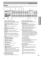
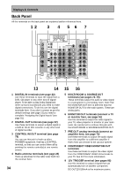
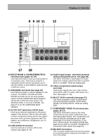
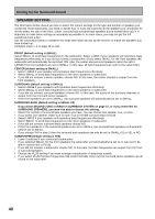
Displays & Controls PREPARATION PREPARATION 8 9 10 11 12 ASSIGNABLE MONITOR OUT Y PB 12V TRIGGER (DC OUT12V/ PR 100mA MAX) Y (DVD/LD) IN 1 PB MULTI-ROOM & SOURCE SPEAKERS PR Å REMOTE IN R FRONT L ª Y PB PR RS-232C · (TV/SAT) IN 2 COMPONENT VIDEO AC OUTLET CENTER R SURROUND L SURROUND BACK / ı R L ª · 17 18 10 MULTI ROOM & SOURCE REMOTE IN terminals (see pages 74-79). Use these terminals to hook up a sub-system in a secondary room. This hook up requires a separately sold IR receiver and allows you to use the receiver to hear different audio sources in different rooms. 11 SPEAKERS terminals (see page 25) Use these terminals to connect speakers to the receiver. The FRONT, CENTER and SURROUND terminals are for the main speaker system and the SURROUND BACK speakers can be set to either the main system, the SECOND ZONE, or the MULTI ROOM. See page 37 to set the SURROUND BACK speakers. 12 AC OUTLET (switched, 100 W max) Hook up an external component to the power supply of this receiver. Only do this with audio or video components being used in this system and never hook up heavy equipment (like TVs, heaters, air conditioners, refrigerators, etc.) to this receiver. 13 USB AUDIO IN terminal Use this terminal to connect a PC to this receiver (see pages 71-72). 14 Audio input/output terminals (connect analog components here, see page 20) Use these terminals to input/output the audio signal from analog components (like a cassette deck or turntable). These are analog jacks. 15 Video components input/output terminals Input/output signals from your video components (DVD, VCR, TV tuners, SAT tuners, etc.) here. (see pages 17-19). 16 MULTI CH IN terminals (see page 21) Use these terminals to input a multichannel surround signal (for example, a DVD-Audio signal) in an analog fashion. These are analog jacks. 17 COMPONENT VIDEO IN terminals (see pages 16-17) Use these terminals to hook up the video connections of your video components with this high quality method. Your components will have to have the terminals as well to take advantage of this kind of connection. If you don't connect as per the default settings (see page 16) you need to complete "Assigning the Component Video Inputs" (see page 92). 18 RS-232C Connection 35 This is a future-oriented port that has the possibil- ity on inputting and/or outputting information to/ from the receiver.
-
 1
1 -
2
-
3
-
4
-
5
-
6
-
7
-
8
-
9
-
10
-
11
-
12
-
13
-
14
-
15
-
16
-
17
-
18
-
19
-
20
-
21
-
22
-
23
-
24
-
25
-
26
-
27
-
28
-
29
-
 30
30 -
 31
31 -
 32
32 -
 33
33 -
 34
34 -
 35
35 -
 36
36 -
 37
37 -
 38
38 -
 39
39 -
 40
40 -
41
-
42
-
43
-
44
-
45
-
46
-
47
-
48
-
49
-
50
-
51
-
52
-
53
-
54
-
55
-
56
-
57
-
58
-
59
-
60
-
61
-
62
-
63
-
64
-
65
-
66
-
67
-
68
-
69
-
70
-
71
-
72
-
73
-
74
-
75
-
76
-
77
-
78
-
79
-
80
-
81
-
82
-
83
-
84
-
85
-
86
-
87
-
88
-
89
-
90
-
91
-
92
-
93
-
94
-
95
-
96
-
97
-
98
-
99
-
100
-
101
-
102
-
103
-
104
-
105
-
106
-
107
-
108
-
109
-
110
-
111
-
112
-
113
-
114
-
115
-
116
-
117
-
118
-
119
-
120
 |
 |
