Sony CCD-V8 Operating Instructions - Page 5
Sony CCD-V8 Manual
 |
View all Sony CCD-V8 manuals
Add to My Manuals
Save this manual to your list of manuals |
Page 5 highlights
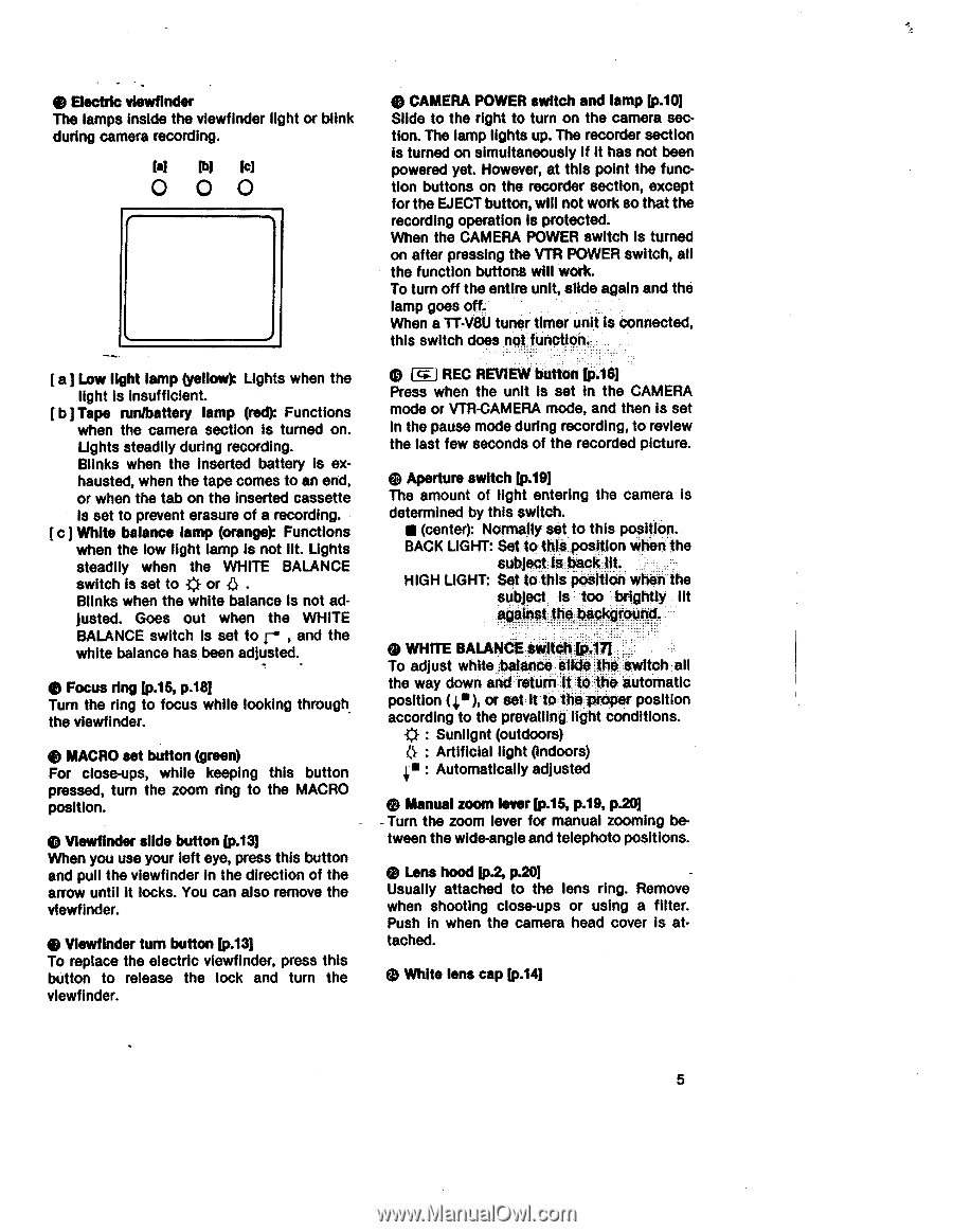
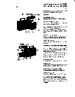
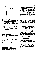
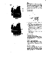
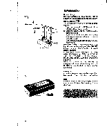
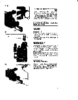
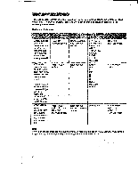
e Electric viewfinder The lamps inside the viewfinder light or blink during camera recording. P)1 Icl O OO [ a] Low light lamp (yellow): Lights when the light is insufficient. [b Tape runlbattery lamp (red): Functions when the camera section is turned on. Lights steadily during recording. Blinks when the inserted battery is exhausted, when the tape comes to an end, or when the tab on the inserted cassette is set to prevent erasure of a recording. [c] White balance lamp (orange): Functions when the low light lamp is not lit. Lights steadily when the WHITE BALANCE switch is set to * or 0 . Blinks when the white balance Is not adjusted. Goes out when the WHITE BALANCE switch is set to r , and the white balance has been adjusted. e Focus ring [p.15, p.181 Turn the ring to focus while looking through_ the viewfinder. e MACRO set button (green) For close-ups, while keeping this button pressed, turn the zoom ring to the MACRO position. 4) Viewfinder slide button [p.13] When you use your left eye, press this button and pull the viewfinder in the direction of the arrow until it locks. You can also remove the viewfinder. 4) Viewfinder turn button [p.13] To replace the electric viewfinder, press this button to release the lock and turn the viewfinder. • CAMERA POWER switch and lamp [p.10] Slide to the right to turn on the camera section. The lamp lights up. The recorder section is turned on simultaneously if it has not been powered yet. However, at this point the function buttons on the recorder section, except for the EJECT button, will not work so that the recording operation is protected. When the CAMERA POWER switch Is turned on after pressing the VTR POWER switch, all the function buttons will work. To turn off the entire unit, slide again and the lamp goes off. When a TT-VtiU tuner timer unit is connected, this switch does not function. (---IREC REVIEW button [p.161 Press when the unit is set in the CAMERA mode or VTR-CAMERA mode, and then Is set in the pause mode during recording, to review the last few seconds of the recorded picture. (1) Aperture switch [p.19] The amount of light entering the camera is determined by this switch. • (center): Normally set to this position. BACK LIGHT: Set to this position when the subject is back lit. HIGH LIGHT: Set to this position when the subject is too brightly lit against the background. (9 WHITE BALANCE switchIp.17] To adjust white balance Slide the switch all the way down and return it to the automatic position (c), or set it to the proper position according to the prevailing light conditions. * : Sunlignt (outdoors) : Artificial light (indoors) 4. : Automatically adjusted e Manual zoom lever [p.15, p.19, p.20] - Turn the zoom lever for manual zooming between the wide-angle and telephoto positions. 4) Lens hood [p.2, p.20] Usually attached to the lens ring. Remove when shooting close-ups or using a filter. Push in when the camera head cover is attached. 4) White lens cap [p.14] 5
-
 1
1 -
 2
2 -
 3
3 -
 4
4 -
 5
5 -
 6
6 -
 7
7 -
 8
8 -
 9
9 -
 10
10 -
 11
11 -
12
-
13
-
14
-
15
-
16
-
17
-
18
-
19
-
20
-
21
-
22
-
23
-
24
-
25
-
26
-
27
-
28
-
29
-
30
-
31
-
32
-
33
-
34
-
35
-
36
-
37
-
38
-
39
-
40
-
41
-
42
-
43
-
44
-
45
-
46
-
47
 |
 |