Toshiba Tecra M2-S410 Instruction Manual - Page 144
Power and Power-up Modes, for details., Two screws secure the keyboard.
 |
View all Toshiba Tecra M2-S410 manuals
Add to My Manuals
Save this manual to your list of manuals |
Page 144 highlights
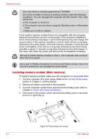
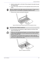
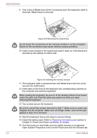
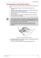
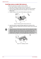
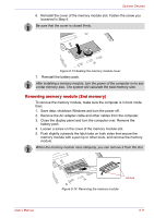
Optional Devices 9. One screw of Metal brace which is pressing down the keyboard cable is removed. Metal brace is removed. Figure 8-8 Removing the metal brace Do not touch the connectors on the memory module or on the computer. Debris on the connectors may cause memory access problems. 10. Insert a new module in the socket and push it down so it lies flat and is secured by two latches on either side. Figure 8-9 Installing the memory module 11. The keyboard cable is pressed down with Metal brace and one screw secures the metal brace. 12. Insert tabs on the front of the keyboard into corresponding notches on the computer and seat the keyboard. When seating the keyboard, be sure to fit the flexible printed circuit board under the palm rest if the flat cable was pulled out while you were removing the keyboard. 13. Two screws secure the keyboard. Be sure to use all two screws removed in step 7. Make sure no screw was dropped into the computer. Make sure all foreign matter, such as the tape applied in step 10 is removed. 14. Seat the keyboard brace and press to secure latches. 15. Install the battery pack. Refer to Replacing the battery pack section in Chapter 6, Power and Power-up Modes, for details. 16. Turn the power on and make sure the added memory is recognized. Open System Properties in the Control Panel and click the General tab. 8-8 User's Manual
-
 1
1 -
2
-
3
-
4
-
5
-
6
-
7
-
8
-
9
-
10
-
11
-
12
-
13
-
14
-
15
-
16
-
17
-
18
-
19
-
20
-
21
-
22
-
23
-
24
-
25
-
26
-
27
-
28
-
29
-
30
-
31
-
32
-
33
-
34
-
35
-
36
-
37
-
38
-
39
-
40
-
41
-
42
-
43
-
44
-
45
-
46
-
47
-
48
-
49
-
50
-
51
-
52
-
53
-
54
-
55
-
56
-
57
-
58
-
59
-
60
-
61
-
62
-
63
-
64
-
65
-
66
-
67
-
68
-
69
-
70
-
71
-
72
-
73
-
74
-
75
-
76
-
77
-
78
-
79
-
80
-
81
-
82
-
83
-
84
-
85
-
86
-
87
-
88
-
89
-
90
-
91
-
92
-
93
-
94
-
95
-
96
-
97
-
98
-
99
-
100
-
101
-
102
-
103
-
104
-
105
-
106
-
107
-
108
-
109
-
110
-
111
-
112
-
113
-
114
-
115
-
116
-
117
-
118
-
119
-
120
-
121
-
122
-
123
-
124
-
125
-
126
-
127
-
128
-
129
-
130
-
131
-
132
-
133
-
134
-
135
-
136
-
137
-
138
-
 139
139 -
 140
140 -
 141
141 -
 142
142 -
 143
143 -
 144
144 -
 145
145 -
 146
146 -
 147
147 -
 148
148 -
 149
149 -
150
-
151
-
152
-
153
-
154
-
155
-
156
-
157
-
158
-
159
-
160
-
161
-
162
-
163
-
164
-
165
-
166
-
167
-
168
-
169
-
170
-
171
-
172
-
173
-
174
-
175
-
176
-
177
-
178
-
179
-
180
-
181
-
182
-
183
-
184
-
185
-
186
-
187
-
188
-
189
-
190
-
191
-
192
-
193
-
194
-
195
-
196
-
197
-
198
-
199
-
200
-
201
-
202
-
203
-
204
-
205
-
206
-
207
-
208
-
209
-
210
-
211
-
212
-
213
-
214
-
215
-
216
-
217
-
218
-
219
-
220
-
221
-
222
-
223
-
224
-
225
-
226
-
227
-
228
-
229
-
230
-
231
-
232
-
233
-
234
-
235
-
236
-
237
-
238
-
239
-
240
-
241
-
242
-
243
-
244
-
245
-
246
 |
 |
